|

Check back often, I will add more Pictures as I complete
the projects. |
|
|
|
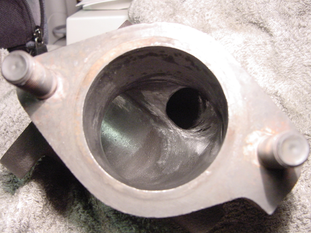
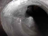
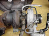
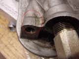
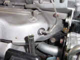
My ported O2 housing. |
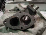 |
I bought this housing off one of the club members, and
decided to open it up a bit more. |
|
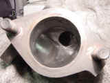 |
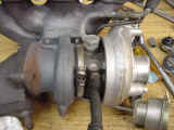
Here you can see how much the bypass opening was
angled more towards the outlet for better flow. |
|
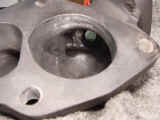 |
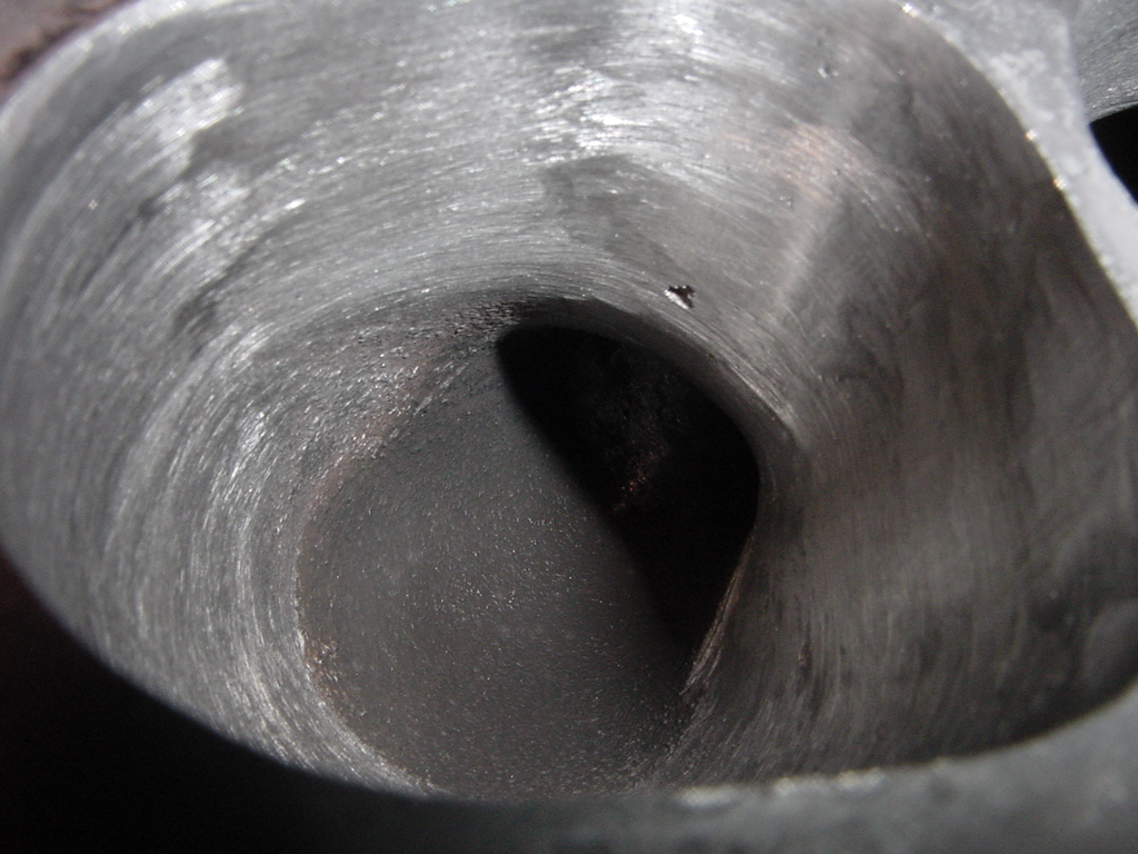
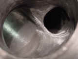
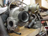
This view shows how much of the lip was taken down to
achieve the opening of the bypass port. |
|
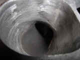 |
Here I used a dremel and a sanding drum to smooth out
the opening and then finished with a wire brush. |
|
 |
A close up of the polishing. I didn't get too hung up
on a mirror finish, I just tried to remove the rough burrs. |
|
 |
A close-up of the exit portion of the wastegate path. |
|
|
16G Install
|
|
My thoughts here are to do a Before and after
comparison. it seems to me it would be the best way to describe the actual
turbo swap. (Also as I went through all the pictures, it almost seemed
like I took a lot of the same types of shots on each turbo which helps.)
As I go through these pictures I will try to point out
areas of concern or interest during the install.
|
 |
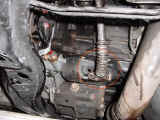
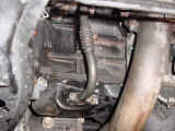
Obviously one of the first things to do is drain the
antifreeze. |
|
 |
And even after draining the fluid there still remains
a significant amount in the head. Keep the bucket handy! |
|
 |
The oil lines also need to be drained. |
|
 |
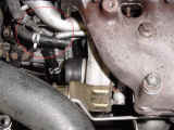
Don't forget to break this oil connection it will make
things easier to remove. |
|
 |
Then if you opted to use the RRE Stainless line you
need to remove the oil connection to the oil filter bracket. |
|
 |
After the oil line and original adapter are removed
install the supplied 90 degree adapter.
Be sure to remove the oil pressure switch, but becareful putting
it back in. (7 foot lbs! don't over torque it!) |
|
 |
Disconnect any additional hoses . |
|
 |
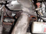
Undo all the mani bolts and pull her out! (Of course
there are a lot of nuts and bolts to undo on the manifold and
exhaust.) |
|
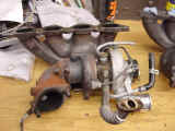 |
I chose to take the whole assembly out attached to the
manifold.
Because... |
|
 |
I had previously purchased a 2G manifold for my 1G,
and when I wrecked her I took it all apart and kept the assy.
together. |
|
 |
Here is a close-up of the T-25. |
|
 |
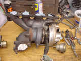
And the new 16G. |
|
 |
Another picture of the 16G. |
|
 |
I was able to use both of the 2G water lines. However
I had to remove the soldered on mounting brackets. but with the
slightest of bending I was able to get the 2G lines to line up in
the factory locations. (Without swapping the top line to the bottom
and vise-versa as mentioned in previous articles on this mod.) |
|
 |
Use a lot of your "buddy" antisieze on all
the exhaust bolts. (It will save you a lot of grief in the future if
you ever have to pull things apart again.) |
|
 |
New gaskets on the reused 1G oil return line. |
|
 |
This picture doesn't show it exactly, but, I had to
trim approximately 4" off the 2G LIC pipe. it made for a
perfect fit onto the Extreme motor sports "J" pipe. |
|
 |
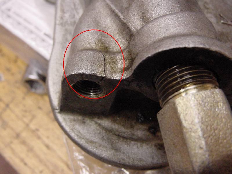
Well this you don't normally have to do, but I had a
major BRAIN FART and over torqued the oil pressure switch, cracking
the oil filter bracket. so I had to take that whole assy. apart.
Bummer! |
|
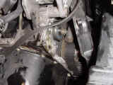 |
Here is the fun you will experience if you aren't
careful.
You have to take all the lower belts off, the crank pully, and
about 6 bolts out of the timing cover. Then if you are
"Lucky" you can pry the case away from the motor enough to
get to the one bolt holding the filter bracket assy. on without
breaking the case... well, I wasn't so lucky, I cracked the case,
but was able to get the bracket off. |
|
 |
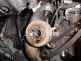
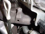
A close-up of the crack that I made. believe me, this
little crack dumped about 1 &1/2 quarts of oil on the floor
after about 3 minutes of idling. |
|
 |
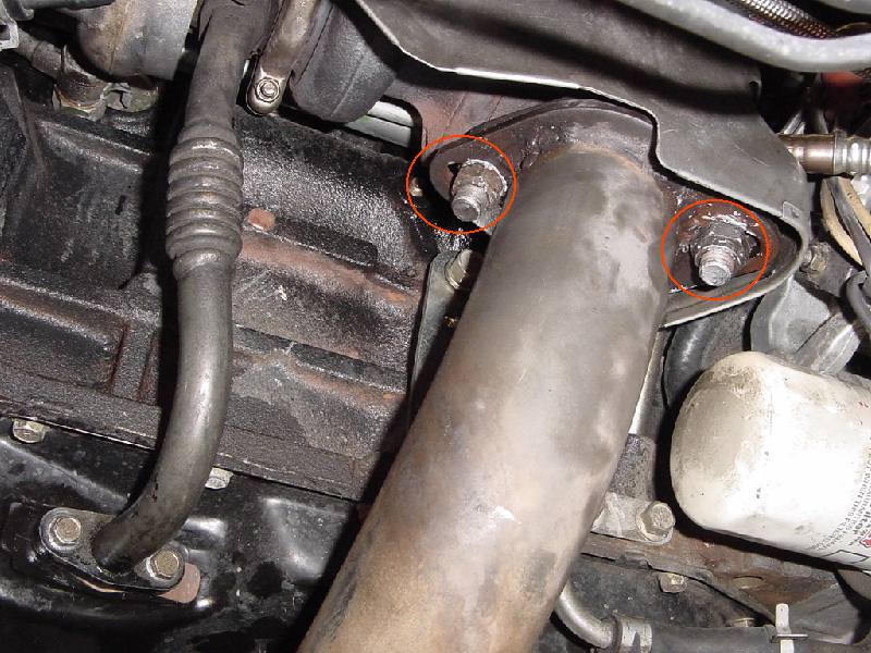
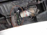
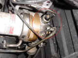
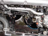
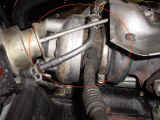
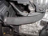
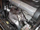
Here is a good view of the 2G turbo on the car. I used
a lot of penetrating oil to remove the nuts, and was very lucky. I
had no broken manifold studs! |
|
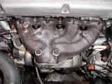 |
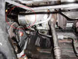
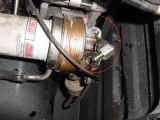
Here is the 16G installed. |
|
 |
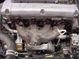
Finally. The before.... |
|
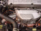 |
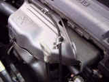
And the after. It looks like it came that way from the
factory! (with the exception of the "J" pipe of course. |
|
|
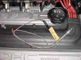
EGT Gauge Install
|
|
Here I am installing my EGT Gauge with the help of my buddy
Tim. He did all of the exhaust work (drilling, tapping, measuring etc.)
and I did all of the electrical work to make things run a bit quicker.
First a little about the parts.
I purchased a VDO EGT gauge on line from "egauges.com".
I ordered the complete kit with wiring and probe. (Part No: 310-153) After
a little further research I found out the probe was too slow reacting, and
I should have gone with an exposed tip probe. I found the faster reacting
exposed tip probe at TRE's
Web page. If I were to do it over again obviously I would just order
the VDO gauge from egauges and the probe from TRE. I wanted this probe
because other probes I have seen such as the probe from Weisach have a
funky hose clamp to attach the probe to the exhaust manifold. I didn't
like that design, and wanted to go with a screw in type of probe. the TRE
probe was perfect. it was a 1/8" npt Genuine aircraft quality type
"K" probe. it came with the mating connector so that if the
probe goes bad you can just order another from TRE unscrew and replace as
needed.
|
 |
Here is the "before" picture. |
|
 |
Here is the exhaust manifold after removing the heat
shield, drilled and ready for the probe. |
|
 |
A better view of the hole location. It is obvious by
the thicker material as to why we chose this location. |
|
 |
This is the TRE exposed tip probe. It is very good
quality, and has a nice strain relief spring on the back of the
probe to protect the wiring. |
|
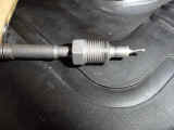 |
A close-up. Notice how short the probe is so you will
not have to worry about the tip touching the inside of the exhaust
manifold. |
|
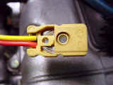 |
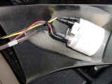
Here is the mating connector that came with the probe.
The color codes are listed in the VDO gauge instructions. In this
case the yellow wire is the positive (+) and the red wire is the
negative (-) connection. They are marked on the connector. Pay
attention to the way the wires are inserted to the connector though.
They slip through 2 tiny holes and then are clamped. |
|
 |
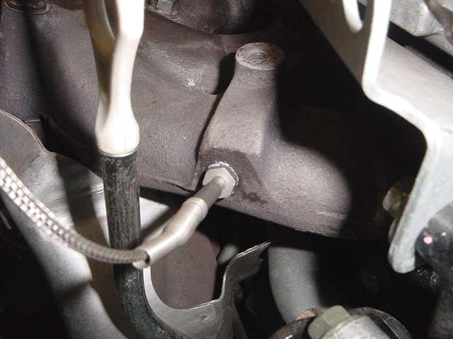
Here the exhaust manifold has been tapped, and the
probe inserted. be sure to use plenty of antisieze compound around
the threads so that if the probe goes bad you can remove it easier. |
|
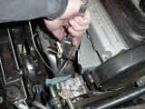 |
Here my buddy Tim is doing some measuring for the heat
shield hole location. (It is nice having the right tools!) You can
pick up a set of dial calipers from Harbor Freight Tools pretty
inexpensively. I wouldn't do anything with out them! |
|
 |
See how perfectly things line up? And if the probe
goes bad. I wont need to remove the heat shield to get to the probe! |
|
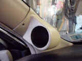 |
Ok on the interior, I used the Gauge pod to mark my
holes. |
|
 |
Here you can see the basic hole locations. |
|
 |
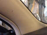
I then rechecked the hole locations, and drilled for
the screws that came with the Lo-Tek
gauge pod. |
|
 |
Here is the VDO Gauge as I was wiring it. |
|
 |
I chose red for +12v and yellow for the lighting. I
jumpered the negative (-) of the gauge lighting and the gauge
together. which turns out as a mistake. I should have separated the
two grounds because (I forgot) that in order to have the nice
"dimming" illumination as the rest of my dash lights, I
needed to attach the ground to the dash light ground. (that is what
is varied, the 12v is constant.) So my gauge lights come on when the
lights are turned on, but doesn't adjust like the rest do.. DUH! Oh
well I can live with it... for now. hehe. |
|
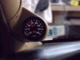 |
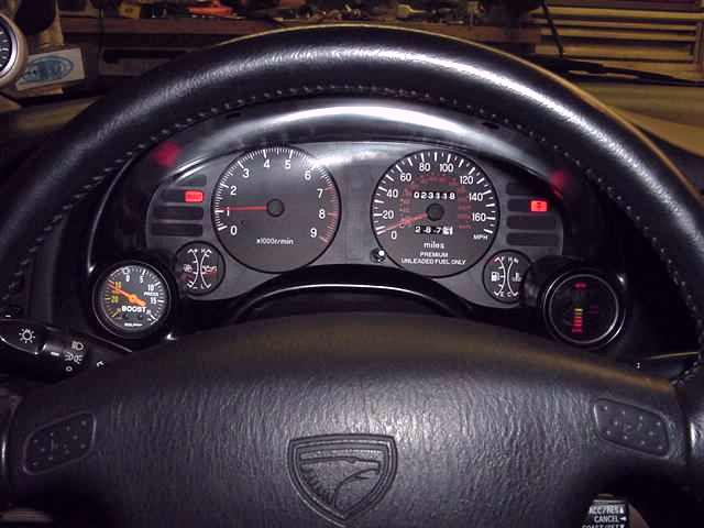
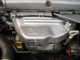
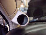
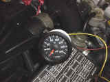
Here is the Gauge installed and working. I forgot to
install the nice little screw "buttons" they supplied with
the gauge for this picture. |
|
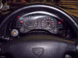 |
And here is the location of my Autometer gauge works
gauge pod for my boost and Cyberdyne a/f gauge. |
|
|
3M Clear Bra Install
|
|
I have been wanting to get my car protected with the Clear Bra Protectant
ever since I have seen the product. I have a standard Bra that came with
the car when I purchased it, but it was starting to rub the paint a bit.
So every now and again I would pull it off to let the paint Breathe. Well
needless to say then I started to get some minor chips on the nose...
Dammit! I used a little touch up paint and hit all the larger dings, and
was debating now whether I should go with the Clear Bra. I emailed Norm
Schilling (A bud from CODSM) who does
window tinting and 3M Clear Bra stuff and asked him if it would be feasible
to still do the Bra. He took a look and said it would be fine, the
chipping wasn't that bad yet. Well, long story short here are some
pictures of the results:
|
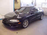 |
Here is the Before shot. (love that car!) |
|
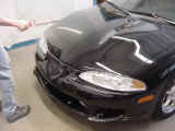 |
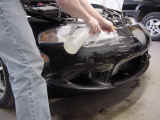
Norm starts by spraying down the front end with a
mixture of alcohol and water to remove any debris. |
|
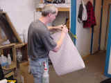 |
As you can see the mask is actually like a decal (as
opposed to a spray on as some people think) that is 8 mil thick but can be removed without damage to the paint if needed. |
|
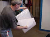 |
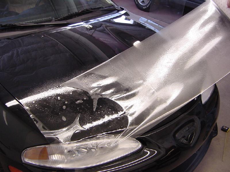
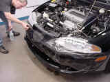
Here Norm peels away the backing, and then he sprays
the clearbra, and the area to be covered with the alcohol mixture. |
|
 |
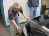
Norm suggested that we go with an 18" wide piece
across the hood for maximum coverage. |
|
 |
He keeps the hood nice and wet with his spray solution
so the clearbra
can be positioned into place. |
|
 |
Norm takes careful measurements so that the clearbra
is
even. |
|
 |
Again after double, and triple checking the position,
he starts to squeegee the clearbra
into place starting from the center
and working outwards. |
|
 |
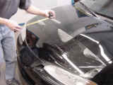
Then once the clearbra
has been squeegeed, he goes back
and trims the clearbra
approximately 3/8" out from the edges. This
way the edges can be rolled under the hood for a better finish. |
|
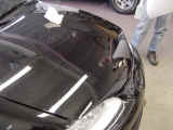 |
Here is the finished hood.. Now on to the nose. |
|
 |
Normally the hood followed through to the fenders is
all that is covered but I wanted the extra protection on the nose
also. |
|
 |
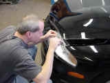
After Norm gets the piece into position he starts in
the center and works his way out. He then trims around the lights.
This area can be very problematic, due to the multiple contours. |
|
 |
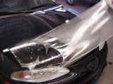
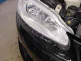
But with a lot of careful trimming, and working all
the air out of the "peaks" you get a pretty good result.
You can tell there is some distortion around the headlights, but it
is a small cost for the protection. |
|
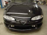 |
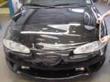
The finished product. I had the leading edges of the
mirrors, and the headlights covered also to minimize chips and
fogging on them in the future. (Typical of the 2G DSMs) |
|
|
|
|
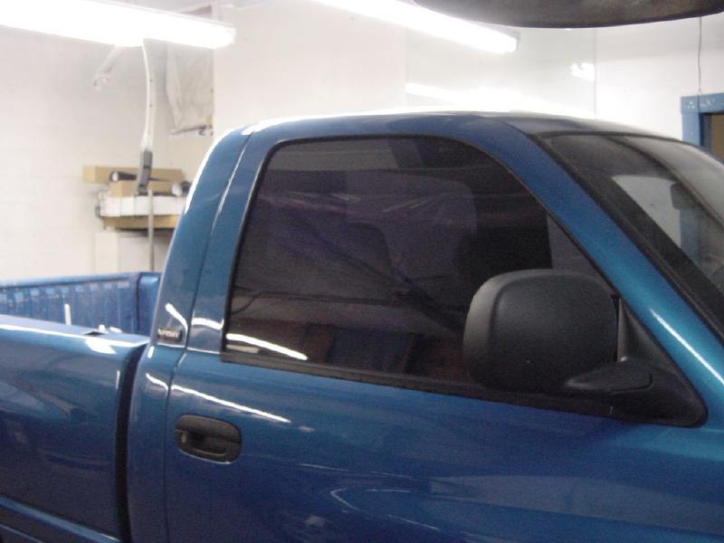
I also wanted to show some of Norms tinting. He does a great job. He
tinted 3 vehicles in addition to doing my Clear
Bra install. This
particular truck had the typical tint job on the sides and in the
back. Norm knocked this out in about 40 minutes.
|
|
The Before
|
|
|
|
|
The After
|
|
|
|
|
If you would like to get a hold of Norm Schilling to have some work done
or get a quote on the Clear
Bra / Window Tinting you can reach him by
emailing him Here:
 Email
Norm Schilling Email
Norm Schilling
|
|
|
|