|
BRITISH ARTILLERY IN WORLD WAR 2 |
|
FIRE PLANNING |
|
Updated 6 June 2014 |
|
|
|
|
|
|
|
|
|
|
|
|
|
|
|
|
|
|
|
|
|
|
|
|
|
|
|
|
|
|
|
|
|
This page describes the British approach to fire plans used to support attacks by infantry or armoured forces - offensive fire plans. Other types of fire plan, such as defensive, counter battery (CB) or harassing, are not dealt with in detail on this page. During World War 2 (WW2) the term 'fire plan' was used in a broad way for any artillery fire that was coordinated with the actions of the supported arm. It could be a simple as a Forward Observation Officer (FOO) ordering a smoke shoot to screen a company while it made a tactical withdrawal or as complicated as a corps fire plan involving 25 regiments firing a barrage 4 miles wide, 3 miles deep lasting several hours and planned days ahead, or even larger in the case of major attacks such as the Rhine crossing.
Internally the artillery term for fire supporting an attack, other than an immediate simple fire plan, was 'programme shoots'. Fairly self-explanatory - 'shooting to a programme'. Despite the name they could be 'on-call' as well as scheduled on a timed programme, and the targets a mixture of ranged and registered or predicted. These shoots could be barrages, concentrations or smoke screens, or any combination of them. The term 'barrage' had a precise meaning, it meant that fire was not directed at specific targets, it was put down in successive lines across an area. In contrast a 'concentration' was aimed at a specific target area and a single aimpoint for every troop's, pivot gun and while the term implied concentrated fire from several batteries it could be a single troop engaging a particular target.
Fire plans are in contrast to 'impromptu targets' although possible opportunity targets could be planned for. For example in an attack fire plan defensive fire (DF) targets could be planned on places where counter-attacks were possible. These planned targets were not 'scheduled', they were on-call, usually with particular fire units assigned to them. Of course additional fire units could be added if necessary. Similar principles applied to DFs protecting a defensive position. Impromptu targets were generally unplanned, although they might be needed during a fire plan if a unexpected situation emerged. However, registered targets (which may or may not have been previously ranged) could also be engaged as impromptu targets outside a fire plan.
Major fire plans were not limited to field artillery, and non-artillery mortars were sometimes used in even the smallest ones. Larger fire plans were also used and in the last months of the war included a substantial `pepperpot' component. This was the term for extensive use of non-field artillery fire. It included 40 mm LAA guns, tanks, mortars and medium MGs. Aircraft, including heavy bombers could also be part of the fire plan, as could gun and rocket fire from ships and landing craft. No matter what the source of the fire power, fireplans for the land battle were made and coordinated by artillery commanders and staffs.
Fire planning and its use and processes evolved continuously throughout the war, with the general goal of speeding up their preparation and increasing their flexibility. Quick fire planning techniques for use in support of company and battalion attacks also emerged, usually used by artillery regiments and batteries.
Although there was a stage when entirely on-call attack fire plans were popular, this was short lived and the accepted tactic in European theatres became a mix of time scheduled and on-call targets, with concentrations overlaid on and around barrages. On-call fire plans of concentrations were preferred in Burma because of the difficulties in estimating movement time through jungle. Silent fire plans were also used, particularly for night attacks, they generally used on-call concentrations fired when the enemy discovered the attack.
Smoke screens could be fired as part of a larger fireplan. However, they might also be fired separately for some purpose. Nevertheless a smoke screen invariably involved careful planning and coordination with the supported arm that it was to assist. The page includes details about smoke screens.
The barrage tended to be the main feature of British major attack fire plans, with concentrations fired in and outside it, both in space and time. Most of the effort in a barrage went into covering fire (CF), ie neutralisation. However, there was usually a preparation element to cause casualties and damage, which could involve both barrage and concentrations. DF targets were planned to help protect captured objectives from counter-attacks and could be concentrations or standing barrages - a single barrage line. CB targets were engaged, including the use of bombards, usually concentrations. Counter-Flak targets, called `Apple Pie' in European theatres, were included in major fire plans when air support was incorporated, again usually as concentrations. HF (Harassing Fire) tasks might be included if resources allowed, although only a few guns were needed, but were unusual in smaller fire plans.
As the war progressed, fire plans of concentrations became common, the guns usually fired with lines of fire parallel as at multi-battery impromptu targets. One technique was to group several concentrations in an area under a code name, with fire control orders being applied to all targets in the named group. In the last months of the war in NW Europe major fire plans made great use of stonks and standing barrages as concentrations. In large fire plans some targets for concentrations would be selected by the attacking battalions and brigades and their supporting artillery commanders. These were sent to the artillery commander's staff for co-ordination and incorporation in the plan.
A barrage was a belt of fire that could be stationary (standing), for example as defensive fire, or moving in front of the assaulting troops. They were arranged in unit lanes with lines across them, the line nearest own troops was the 'Opening Line'. In a barrage the guns fired at the lines, a troop's guns' aim-points spread equally along each line's troop lane width.
Barrages could be regular in shape (a rectangle) or irregular. Quick barrages were introduced in the middle of the war and the older type of barrage was sometimes called an 'ordinary barrage'. Quick barrages had to be rectangular shaped and orders could be issued by radio, ordinary barrages could be any shape, were usually quite large and orders were issued as traces that were overlaid on maps.
Moving barrages had as many lines as needed to achieve the depth required. They could be either creeping, rolling or block. When creeping, each line was engaged in turn, when fire lifted from the front-most line it moved backwards to the next line (a-a, then b-b, etc in Figure 1). In rolling, several lines were engaged at once with overlapping times (eg a-a & b-b, when fire lifted from a-a it went to c-c with fire continuing on b-b until it lifted to d-d). A block barrage had several lines engaged simultaneously and all lifting together to a new block (eg a-a, b-b & c-c lifting together to d-d, e-e & f-f). Creeping was normally used for dismounted infantry attacks, rolling for tank and mounted ones. Moving barrages could also be 'dragnets' during preparation fire, in these the barrage could be repeated and move backwards as well as forwards. A standing barrage was one that didn't move, it had one or more lines and was typically used to prevent interference with an attack or for defensive fire.
Figure 1 - Regimental Moving Barrage
Some important terms used with barrages were:
A 25-pdr troop could effectively cover a lane with 140 yards maximum width, lines were usually 100 yards apart. For a creeping barrage normal practice was for a field regiment to engage a regimental lane two batteries wide (560 yards maximum), with the third battery superimposed across the full width of the depth lane (ie open on b-b in Figure 1). For a dismounted infantry assault a regimental lane was normally 400 yards wide, the full width being used with armour. However, lanes could vary in width in a fire plan.
In addition to lettering each line the corners of the barrage were also lettered, starting at the right-hand end of the opening line. If the opening and or final lines had turns these too were lettered and turns were always at lane boundaries. Intermediate lines were also lettered and called Key Lines. These letters, by convention capital letters, were given their accurate map coordinates and so provided the spatial framework of the barrage.
Simplicity in barrage design was always the goal and so a regular shape was preferred and was essential for a quick barrage. However, irregular shaped barrages could be used in which lines were not straight for the entire width, had boundaries of different length and or lanes changed direction. Width could also be changed. There were two methods for changing lane direction. In the 'wheel' method the distance between lines varied but lines remained the full width of their lane. In 'echelon' the length of the lines varied in length. The two are shown in Figure 2.
Figure 2 - Barrage Turning Methods
The need for the infantry to `lean' on the barrage had been well established in WW1. Indeed the French considered that the attacking infantry could expect 10 - 15% casualties from their own artillery fire if they were about the right distance from it, and once in that war the British order was to keep 25 yards from the barrage! More generally the British took the view that to reduce casualties from defenders to the absolute minimum the assault had to reach its objective within about two minutes of fire lifting from it, whether a barrage or concentration. More than this and the enemy had time to decide that the fire had lifted and then re-occupy their battle positions. Obviously poor quality troops took longer, and it also took longer for defenders in deep bunkers or cellars to get to their fighting positions.
Keeping the attacking forces 'on course' could also be a problem, map reading across devastated terrain wasn't always easy and the chance of the attacking troops swinging off their axis or getting the wrong distance from the fire was always a hazard. One of the advantages of a continuous barrage moving steadily forward was that the infantry at least knew where they had to be in relation to it, which reduced the chance of fratricide from the infantry being in the wrong place when fire opened on a target. Coloured smoke or flares provided one way of signaling events in a fire plan, and from 1942 LAA fire (tracer) was used in major barrages to indicate its boundaries and infantry lanes within it.
However, the main problem was to keep the enemy neutralised in their protective shelters after the fire lifted and until the attacking infantry were on the position, and fire plans included deceptive measures to achieve this. Various techniques were used to vary the firing pattern of a barrage, for example it might start on the final line, move forward then move back again. This was sometimes called a 'dragnet' barrage. False and different sequences of lifts were used if a barrage was repeated, ie used for preparation as well as covering fire. One goal was to try to get the enemy into their battle positions and fire at them again, this might be repeated to lull them into staying under cover when the real lift came as the assaulting infantry approached. This technique was also used with concentrations.
Barrages (and concentrations) could be entirely predicted to achieve surprise, this was the case at Cambrai in 1917 when a predicted barrage was first used. Ranging was essential if firing units were not on a common survey grid. However, at least one point in a barrage was usually ranged and registered, generally a junction of the opening line and a lane boundary. But it could be a clearly defined point on the ground within a lane that could be related to a junction on the opening line, so a clearly defined point was usually selected for this. For barrages with an irregularly shaped opening line, changing direction at lane junctions, then each direction changing junction and the outer-most lane edges had to be registered. Fire plans of concentrations might need considerably more registration because each concentration was a separate target. However, the general practice in any fire plan was to minimise ranging because of the risk of compromising tactical surprise.
A characteristic of all British fire plans was 'superimposed units' to provide a reserve. These were used to engage on-call targets, particularly DFs, or even entirely unplanned ones. The doctrine was that they could be removed from a scheduled task without significantly affecting the success of fire on that task. For smaller fire plans they were usually the supporting battery or regiment of the battalion or brigade making the attack because the observers had the most direct communications with them. The availability of superimposed units meant that the non-superimposed units committed to the timed program were sacrosanct.
The main planning issue was to deliver sufficient intensity of fire, a matter of density and duration. In a barrage this meant the appropriate rate of fire onto each line for sufficient time. This time was governed by the rate of advance but it was generally considered that a line had to engaged for at least 2 minutes. If the advance was fairly fast then it might be necessary to engage more than one barrage line at a time without counting the superimposed units, hence the use of rolling barrages in mounted attacks.
The opening line of a barrage was always positioned in front of the enemy's most forward positions, and some distance in front of the attacking troop's start line. Field gun safety distances for dismounted infantry were 150 yards if the line of fire was overhead and 200 yards if fire was from a flank, see Table 1. Medium artillery had to engage lines at least 300 yards back from the opening line. The opening line was engaged for long enough for the assaulting troops to move from their start line to within 150 or 200 yards.
However, a problem with deep barrages was 25-pdr range, maximum range was some 13,400 yards with charge super but the guns overheated after about 40 rounds at this charge. This meant that in barrages 25-pdr were usually limited to charge 3 and a maximum range of about 11,800 yards (usually less with Sexton) with typical battery deployments this gave a barrage depth of about 8000 yards. If deeper was required the solution was to engage the deep lines with medium artillery, although this presented troop safety problems. It might also be possible to move field batteries forward as the barrage advanced, not least because it may have been possible to reconnoitre and survey gun positions close to what had been friendly FDLs.
1943 planning data is shown in Table 1, the safe distance was for a line of fire parallel to the front of the assaulting troops, these were reduced for overhead fire. These figures applied to both barrages and concentrations. There were some differences post war.
Table 1 - Planning Data (yards)
|
Term |
25-pdr Gun |
3.7" How |
4.5" Gun |
5.5" Gun |
155-mm Gun |
7.2" How |
|
Frontage covered by HE shell |
35 |
35 |
55 |
70 |
70 |
100 |
|
Safe Distance |
200 |
200 |
350 |
400 |
400 |
700 |
The subject of safe planning distances needs further explanation. Figure 3 shows the lethality pattern for a 25-pdr HE ground-burst shell with angle of descent 20º and the percentage casualties to men standing in the open around the point of burst of the shell. The likelihood of casualties to men in a 'protective posture' was far less. At higher angles of descent the `butterfly' pattern is less pronounced and the lethal area becomes more circular as it approaches 90º. Outside the `wings' there was still a very small chance of a casualty, obviously this increased as more shells were fired. The safe distances were planning distances providing an acceptably low chance of a casualty, although higher than would be acceptable in peacetime.
Figure 3 - 25-pdr Lethal Area

Table 2 - Example 25-pdr Ranges and Probable Errors
|
Charge |
Angle of Descent |
Range |
50% Zone (range/line) |
Max range for charge |
|
1 |
20º |
2,600 yds |
60/2 yds |
3,900 yds |
|
2 |
20º |
5,000 yds |
30/2 yds |
7,800 yds |
|
3 |
20º |
7,000 yds |
20/3 yds |
11,800 yds |
|
Super |
35º |
11,000 yds |
50/6 yds |
13,400 yds |
The difficult part of a barrage was planning the timings for the rate of advance and for the assaulting troops to maintain the planned rate of advance and so keep close to the barrage. This was exacerbated by the inability to modify a large barrage once fire was opened. The problem was the sustainable rate of advance to keep up with the irrevocable movement of the barrage. One technique used to help the assaulting troops was to insert pause lines into the barrage, on which fire would dwell to give them an opportunity to catch up if necessary. Some commanders were not keen on this, taking the view that it caused the attack to loose momentum. Of course this problem of coordinating the movement of attacking troops with CF existed in any fire plan, whether it involved barrages or concentrations.
In 1918 the normal rate of advance was 100 yards in four minutes and between the wars it was fixed at three minutes on the basis that infantry loads had lightened. In mountainous terrain, such as Italy, 100 yards in 15 minutes proved unachievable. In Holland in 1944 a rate of 100 yards in five minutes held up the infantry. However, a safe distance of 200 yards and a bogey time of two minutes to reach the enemy position after fire had lifted from it meant a rate of 100 yards in 60 seconds! The added complication was that enemy positions had depth and barrage lines were usually 100 yards apart.
There were five alternatives:
In NW Europe it was found that tanks, either alone or carrying infantry, and carrier-borne infantry could advance at 150 or 200 yards per minute by day and 100 by night. The first, sustained demoralisation was also achieved on occasions and pressing closer to the fire was also used.
Concentrations weren't the complete answer either. For a start there was still the problem of getting the infantry to the safe distance from the concentration then lifting it and the time it took them to secure their objective. An added problem was the size of the concentration in its two dimensions, when fire lifted the assault might be several hundred yards from the rear-most positions on the objective. There were several possible solutions to this:
In 1943 it became policy that a concentration should not be more than 200 yards deep when used for CF and this tended to lead to parallel stonks in larger fire plans. They could be engaged simultaneously or sequentially. When concentrations on the objective ceased it became usual to `lift-out' onto targets surrounding the objective, to prevent interference from mutually supporting positions and forestall counter-attacks.
The amount of fire used on a target was a matter for the originator. There were Standing Order rates and quantities for DFs. The normal order for 'fire for effect' concentrations in fire plans was "nn rounds gunfire". 'Gunfire' meant that rounds were aimed and fired as quickly as possible (unless an interval had been ordered). For 25-pdr this was about 6 - 8 rounds per minute, but could only be sustained for a few minutes.
In fire plans, when targets or barrage lines had to be engaged for a particular duration, 'rates of fire' (rounds per minute) were ordered with a duration in minutes. These rates were named and the number of rounds per minute varied depending on the type of gun as shown in Table 3. Intense rate was the maximum sustained rate that the gun could fire without overheating.
Table 3 - Rates of Fire - Rounds per Minute
|
Term |
25-pdr Gun |
3.7-in How |
3.7-in HAA |
105-mm How |
4.5-in Gun |
7.2-in How |
7.2-in How Mk 6 |
155-mm Gun |
8-in Gun |
240-mm How |
|
Intense |
5 |
5 |
12 |
5 |
2 |
1 |
1 |
2 |
- |
- |
|
Rapid |
4 |
3 |
4 |
4 |
1½ |
½ |
1 |
1 |
1 |
2⁄3 |
|
Normal |
3 |
2 |
3 |
3 |
1 |
1⁄3 |
½ |
½ |
½ |
1⁄3 |
|
Slow |
2 |
1 |
2 |
2 |
2⁄3 |
¼ |
1⁄3 |
1⁄3 |
1⁄3 |
¼ |
|
Very Slow |
1 |
½ |
1 |
1 |
1⁄3 |
1⁄8 |
1⁄6 |
1⁄6 |
1⁄6 |
1⁄8 |
The British had introduced smoke shells in WW1, these were bursting shells filled with white phosphorus (WP). Shells were available for 18-pdr, 3.7-inch How and 4.5-inch How. However, WP shells were not ideal, they created smoke instantaneously but being hot the smoke tended to 'pillar', particularly in hot and dry weather and quite a high rate of fire was needed to sustain a screen. In the 1930's they invented Base Ejection (BE) smoke, the smoke creating material was held in canisters that were ejected from the base of the shell in flight and fell to the ground. Each canister emitted smoke for 75 - 90 seconds. 25-pdr was the first gun issued with these shells but at the outbreak of the war there was very little experience with their use. The first written instruction was issued in 1940 and a revised pamphlet issued in 1943. More details about BE smoke shells are on the Ammunition page.
A smoke screen was used to blind an enemy position and screen own troops or the ground they were going to cross. This need to blind and screen governed the positioning of the smoke screen. It had to be between the two areas, and was usually closer to the area to be blinded because this usually had a smaller frontage than the area to be screened.
The smoke cloud drifted with the wind and had several characteristics:
Figure 4 - BE Smoke Cloud
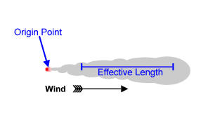
The limited height, effectively about 50 feet, meant the screen had to be placed where the enemy couldn't see over it. An added complication was that the smoke canisters didn't function if they were dropped into water or marshy ground. They could also bounce if their angle of descent was too low and could roll down a steep hillside, which is why WP was retained for 3.7-inch How (primarily a mountain gun).
Local weather conditions were also a factor, and liable to change between planning and firing, not to mention such things as the effects of local terrain on wind direction. The three main recognised factors were:
However, generally only wind speed was taken into account although in some theatres allowance was also made for dry and bright conditions. The standard conditions were wind speed of 15 ft/sec (about 9 knots), 75% humidity and 'standard' turbulence. This required 1.5 rounds per minute per point in a smoke screen. This reduced to 1 rpm for a 5 ft/sec wind and increased to 2 rpm if it was 25 ft/sec. A wind significantly stronger than this would make a screen ineffective.
A smoke screen had two or more origin points in a line, the distance separating these points depended on the line of the screen relative to the direction of the wind. If the wind direction was along the screen line then origin points could be a few hundred yards apart to reflect the effective length of the cloud. However, if the wind was at right angles the origin points were only about the width of the mid-point of effective length apart. An oblique wind somewhere between the two.
Figure 5 - Smoke Screen Layout
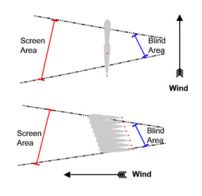
Initially it was considered that one origin point gave an effective length of about 400 yards, this was revised down to 300 yards. For a cross wind the effective width was taken as about 30 yards, which allowed sufficient overlap to maintain a 'solid' screen with local fluctuations in wind direction. However, this distance was increased to 75 yards by sweeping 25 yards when the line of fire was similar or opposite to the wind direction, and recognising the dispersion of the canisters along the line of fire. For an oblique wind the effective length was 150 yards. The ineffective distance was the first 75 yards from the origin point.
The characteristics of smoke and its use were the critical factors in planning a smoke screen, the first critical step being to decide the line and length of the screen to achieve the objectives of blinding and screening. From this and the wind speed and direction the number of origin points could be determined. A screen could require firing by a single troop or up to several batteries.
A smoke screen could be either quick or part of a major fire plan and created by registration or prediction. Initially, it was usual to register each origin point but mid-war the procedure was changed to a single origin (Oboe) point with other points calculated from it. If more than one troop was required, then each troop was given its own section of the screen containing origin points for its guns. A key decision was whether or not to fire a 'tester' to confirm wind conditions at the screen position. The decision had to balance the risk of compromising security and losing surprise by firing a smoke tester against the possibility that the screen wouldn't be effective.
Major fire plans were planned up to days in advance and the smoke screen predicted. This meant the plan had to be changeable at the last moment to accommodate the actual wind conditions. Each screen layout option (for head, tail, flank or oblique finds relative to the screen line) was given a code word and fire units allotted for each option. The screen line was defined by its two end points, P and Q. Alternative HE targets, typically concentrations, were also selected in case the screen failed. An officer was specifically appointed as an observer to control the smoke screen by selecting the best option and order the alternative targets if necessary.
One fire plan technique was to create a lane for advancing armour a few hundred yards wide between two screens, these blinded defiladed anti-tank guns, if the wind was favourable these screens could be rolling. Smoke screens could be sustained for long periods, on at least one occasion all day.
The CRA was usually the fire planner for division and brigade attacks, although in the latter case he would normally leave control of the fire plan to commanding officer of the regiment in support and normally affiliated with the brigade. However, the policy of the regimental commander being with the brigade commander meant that sometimes the fire planner was the artillery commander with the tactical commander of the operation, although for divisional and corps fire plans the detailed work was done by the artillery commander's staff and the CB component was usually planned by the CB Officer or Assistant CB Officer, or later in the war an AGRA staff. In all timed fire plans engagement times were ordered to the whole minute.
Fire plan orders were issued as map traces annotated with times and rates of fire or task tables that gave target map references with engagement details. Figures 6 and 8 provide examples. Producing traces involved considerable work, each field regiment required 10 (one per battery and troop CP plus regimental HQ), plus one for each forward infantry battalion and additional ones for anti-tank batteries and armoured squadrons. A divisional fire plan typically necessitated at least 60 copies of the fire plan trace - and there were no photo-copiers!
For a divisional barrage HQRA would assign regimental lanes, the adjutant of each regiment would then assign battery lanes and finally each CPO assigned lanes to the two troops in his battery. In each case they annotated the issued traces, which were eventually pinned to the artillery board in each troop CP so that firing data would be produced.
Figure 6 - An Example Trace for a Barrage
Figure 6 shows an example trace (not to scale) for a simple divisional barrage involving three regiments. The example is that annotated by the adjutant of 9 Fd Regt for its P battery, with lines f - h deleted because they are not engaged by P battery due to the echelon turn. Other points to note are the coordinates of points A - F, the duration (relative to Zero Hour) of fire on each line and the rates of fire.
The next step was for each batteries' CPs was to calculate data for the barrage key lines, these were either detailed on the trace, (lines A-B, C-D and E-F in Figure 3 - the opening, turning and final lines were always key lines) or a line every 600 yards. Traces were mounted on their Artillery Boards and the switch from zero line and range was measured from No 1 gun in each troop to the intersection of the line and lane boundary and to the battery's other 3 aimpoints on the line and recorded on the Barrage Key Lines Form (AF B2505) for each troop. From this form a Gun Programme Form (AF W3981) was completed for each individual gun with concentrations and position corrections to adjust the data for the position of each gun relative to Number 1 gun. Data for lines between the key lines was interpolated, usually using transparent 'fans' marked with switch angles and ranges. Corrections for non-standard conditions and angle of sight were included in the form to produce firing data. Figure 7 shows an example of a completed Gun Programme (for No 3 gun of B troop) as it would be issued to the gun's Number 1. It is for the trace shown in Figure 6.
Figure 7 - Example of a Completed Gun Programme Form
The process for concentrations was similar. Figure 8 shows an example trace providing engagements details for 6 concentrations to be engaged in a period of 30 minutes. However, for concentrations an alternative to a trace was a task table, particularly if the targets were registered and would be referred to by target number instead of coordinates. This was usually the case for counter-bombardment targets. The task table detailed the times, firing units, rates of fire and ammunition for each target. However, for concentrations there was no interpolation and full calculations were made for every target, again Gun Programmes were usually prepared, depending on the complexity of the fire plan and the time available.
Figure 8 - Example Trace for Concentrations
1942 planning times for units to prepare barrages, from the commander issuing orders, were three hours for regimental, 10 to 12 hours for a division and 24 for a corps. These times include deployment and survey but excluded any ammunition dumping. For a quick (as opposed to `ordinary') divisional barrage, where the guns were already deployed, it was two hours. For a regiment 60 to 80 minutes assuming no more than 10 lines. Timings for fire plans of concentrations were not greatly different, although it would depend on the number of concentrations, analogous to the number of lines in the barrage.
Targets in fire plans were normally fired `time on target' (ToT) from late 1942 (a procedure introduced earlier that year when BBC time signals became available), although if this wasn't explicitly ordered then the ordered times were ataken as firing times, care and time being taken to ensure synchronised time between all the (friendly) participants.
Other gun position procedures required before firing started including preparing all ammunition, testing the guns' sights and verifying that their Zero Line was correct. Normal practice was to rest one gun at a time in each troop for at least 10 minutes per hour from 45 minutes after the start of the barrage, during this time they conducted quick sight tests, cleaned and maintained the gun.
In April 1945 2 NZ Division made a series of divisional attacks in N Italy while acting as 'point' for 8th Army. The fire planning for each of these was probably the epitome of the 'art' involving up to 15 regiments under the CRA's command with the complete artillery plan being made and executed in around 24 hours. Although they were all different, typically the barrage component was about 4000 yards wide and 3000 yards deep. Up to 8 regiments fired dragnet creeping barrages of over 30 lines, each with different lift sequences. In between the barrages the field regiments switched to HF tasks. Other regiments and heavy mortars fired concentrations within and around the barrage lanes and a reinforced AGRA fired CB and counter mortar tasks. Naturally there was a comprehensive DF plan to protect consolidation and re-organisation around the objectives from German counter-attacks.
In 1941 Quick Barrages were introduced at regimental level using standard layouts and CP templates and used simplified procedures. Written orders and traces were not used, details being given verbally by radio, lanes did not turn or alter in width, each troop's angle of sight remained the same throughout the barrage and templates and tabulated data were used in CPs. Since the quick barrage was less accurate, the attack start line was normally 500 yards from the barrage opening line, so fire on that line had to last longer while the assaulting troops closed to the safe distance.
Quick barrages were followed in 1942 by quick regimental fire plans, as part of the introduction of regimental concentrations and authorised observers, they were enabled by the growing and successful use of radio communications although line could be used. Typically, such fire plans were used to support quick battalion attacks and could be planned, with the supported battalion commander, by the regimental commander, regimental second-in-command or a field battery commander. The latter usually controlled the fire plan once it started and gradually became the normal planner, being authorised for the regiment. Quick fire planning became one of the most notable features of the British artillery system.
Quick regimental fire plans were a consequence and benefit of having artillery commanders with the supported arm and the batteries' senior officers forward. This meant that plans had to be simple and relatively small scale, although the procedure enabled quick divisional fire plans including barrages, and so required reduced preparation time.
The critical success factor was for the supported battalion commander and the artillery commander, usually the BC when affiliation had taken root, to plan the targets together by looking at the ground where the operation would take place. It was usual for key targets to be ranged and registered, the tactical circumstances usually meant that total surprise wasn't an issue but speed of action usually was. The process evolved fairly quickly, soon becoming a matter for the battery commander with the supported battalion, the former usually deputed ranging to one or both of his observers.
As the war progressed the techniques and procedures for regimental or BCs' fire plans evolved, and continued the obsession with speed. The time needed to develop them depended on the number of targets. They were particularly useful when operations turned to pursuit or during advances against light opposition. They were usually concentrations using a mix of timed and on-call targets. Increasingly battalion mortars were included in quick fire plans.
FOOs used quick fire plan techniques to support company/squadron actions or perhaps on-call for a patrol. Typically these fire plans comprised no more than a handful of targets, often using just the FOO's own battery.
Modification techniques were introduced so that timings would be altered if the infantry's progress was delayed or accelerated. Three basic states for modifications were established; either no modifications allowed, modifications by an artillery observer from observations or modifications by the supported arm through a BC or FOO.
Copyright © 2003 - 2014 Nigel F Evans. All Rights Reserved.