Serial LCD interface using AVR 90s2313
One of the first things people want to interface to a design is an LCD display, both to
help with debugging their programs and as a way to provide results to the outside world.
Unfortunately LCD's require both a lot of I/O lines (7 at best) and require precise timing
and command structure that sometimes are not easy to achieve.
The easiest way to overcome all these problems is to create a "front end"
to the LCD that will accept serial data and thus require only 1 line from the mcu and
almost no programming effort to display some text.
Before we go into the programming of such a "front end" a few details about how
an LCD works.
 LCD info
Most text displaying LCD's (there are also graphics LCD's) are based on the Hitachi HD44780A LCD controller.
This controller takes care of all the multiplexing and the peculiarities required by the
LCD display and provides a low level command interface for certain actions like screen
clearing, cursor shape and size, character displaying etc.
The HD44780A communicates with the host mcu through an 8 bit bi-directional interface
(D0-D7) and 3 control lines ( E, RS, RW). Table 1 shows the pin connections
Table 1 - PIN CONNECTIONS
| Pin No |
Symbol |
Level |
Function |
| 1 |
VSS |
- |
0V |
Ground |
| 2 |
VDD |
- |
+5V |
Power Supply (+) |
| 3 |
VO |
- |
Contrast |
| 4 |
RS |
H/L |
L : Instruction Code Input
H: Data Input |
| 5 |
R/W |
H/L |
L : Data Write (MCU to LCD)
H: Data Read (LCD to MCU) |
| 6 |
E |
H,H--> L |
Enable |
| 7 |
DB0 |
H/L |
Data Bus lines |
| 8 |
DB1 |
H/L |
| 9 |
DB2 |
H/L |
| 10 |
DB3 |
H/L |
| 11 |
DB4 |
H/L |
| 12 |
DB5 |
H/L |
| 13 |
DB6 |
H/L |
| 14 |
DB7 |
H/L |
LCD's are slow devices when compared to microcontrollers. Special attention must be
paid so the commands and data are not send too quickly from the mcu, and the designer must
control the communication speed and timing to ensure that the slow LCD and the fast mcu
stay synchronized.
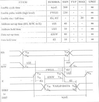
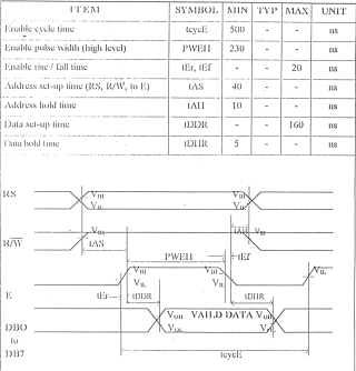
The timing between the mcu and the HD44780A is shown below.
Write Operation

Read Operation

Except the 8 bit interface the HD44780A supports also a 4 bit interface for use with
either 4 bit mcu's or when the system designer is "low" on I/O lines.
This 4 bit mode is essentially the same as the 8 bit mode but data transfers between the
mcu and LCD controller are done in two cycles, a nibble (4 bits ) at a time.
In the 4 bit mode data is transferred using lines BD7-DB4 lines DB3-DB0 are not used. The
high order bit contents are transferred first (DB7-DB4) and then the low order (BD3-DB0).
Since in our design we devote the whole 90s2313 to control the LCD we will use it in the 8
bit mode
 Commands and initialization
sequence
As i have already mentioned the HD44780A provides the user with some commands that control
the behavior of the LCD.
These commands are shown in detail on the controller data sheet
| Instruction |
Code |
Description |
Execution
time |
| RS |
R/W |
DB7 |
DB6 |
DB5 |
DB4 |
DB3 |
DB2 |
DB1 |
DB0 |
| Clear display |
0 |
0 |
0 |
0 |
0 |
0 |
0 |
0 |
0 |
1 |
Clears display and returns cursor to the home position . |
1.64mS |
| Cursor home |
0 |
0 |
0 |
0 |
0 |
0 |
0 |
0 |
1 |
* |
Returns cursor to home position DDRAM contents remains unchanged. |
1.64mS |
| Entry mode set |
0 |
0 |
0 |
0 |
0 |
0 |
0 |
1 |
I/D |
S |
Sets cursor move direction (I/D), specifies to shift the display (S). |
40uS |
| Display On/Off control |
0 |
0 |
0 |
0 |
0 |
0 |
1 |
D |
C |
B |
Sets On/Off of all display (D), cursor On/Off (C) and blink of cursor position
character (B). |
40uS |
| Cursor/display shift |
0 |
0 |
0 |
0 |
0 |
1 |
S/C |
R/L |
* |
* |
Sets cursor-move or display-shift (S/C), shift direction (R/L). DDRAM contents remains
unchanged. |
40uS |
| Function set |
0 |
0 |
0 |
0 |
1 |
DL |
N |
F |
* |
* |
Sets interface data length (DL), number of display line (N) and character font(F). |
40uS |
| Set CGRAM address |
0 |
0 |
0 |
1 |
CGRAM address |
Sets the CGRAM address. |
40uS |
| Set DDRAM address |
0 |
0 |
1 |
DDRAM address |
Sets the DDRAM address. |
40uS |
| Read busy-flag and address counter |
0 |
1 |
BF |
DDRAM address |
Reads Busy-flag (BF) indicating internal operation is being performed and reads
address counter contents. |
0uS |
| Write to CGRAM or DDRAM |
1 |
0 |
write data |
Writes data to CGRAM or DDRAM. |
40uS |
| Read from CGRAM or DDRAM |
1 |
1 |
read data |
Reads data from CGRAM or DDRAM. |
40uS |
Before i continue with the initialization sequence that the mcu must send to the LCD a few
things about the inner workings of the LCD.
The LCD module contains 3 different functional blocks.
The Character Generator ROM (CG-ROM) , the character generator RAM (CG-RAM) and the
Display Data RAM (DD-RAM) .
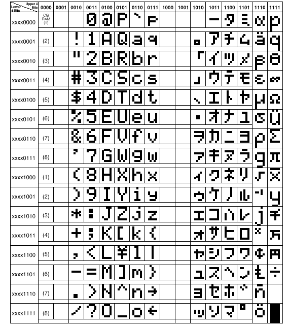
The ROM character generator is factory programmed and contains the 208 characters to be
displayed.
Usually the ROM character generator contains the characters shown in Table 4

The CG-RAM allows the user to define up to 8 special character that are not included in
the CG-ROM.
The DD-RAM holds the characters that are actually displayed in the LCD
Both the CG-RAM and DD-RAM can be read and written (through commands) by the mcu
The most important (and sometimes complex) of the function blocks is the DD-RAM. This has
to do with the way that is implemented and sometimes is different from LCD to LCD
Depending on how many lines by how many rows the LCD can display the DD-RAM address
changes.
Following are the DD-RAM address of some of the most common LCD configurations.
1 Line LCD's

2 Line LCD's

When we power up and initialize the LCD the controller sets the start address of the
DD-RAM to 0. With every subsequent write to the DD-RAM by the mcu the LCD controller
increases the DD-RAM address by one.
You might have noticed that although a 2 lines by 16 character LCD should have 16 bytes
difference between the 1st and 2nd line the difference is greater. This is because the
DD-RAM available for each line is 40 bytes (for the 2 line displays)
So if you are on the 16nth character of the first line and you want to move on the 1st
character of the 2nd line you must tell the LCD controller to move not only 1 position but
24.
If you don't do that then the character is "printed" but is not visible.
Sounds complicated ?
To understand it you have to make a small assumption. You must think that the display area
of the LCD is a kind of a "sliding window", that allows you to see only a
portion of what is behind it, in our case the DD-RAM.
The size of this window is determined by the the characteristics of your LCD, 16
characters in our case.
So if you want to see the 17nth character stored in the DD-RAM you have two options.
Either to move the character inside the "window" or move the "window"
so that the character will be visible.
The second technick can help you create scrolling displays without too many data transfers
between the mcu and LCD.
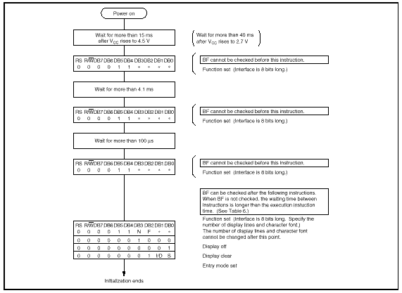
Let's go back to the initialization sequence now.

Now that we have covered the basics about how the LCD works and its functions let's see
how the serial LCD interface is implemented.
Although the 90s2313 is used in this example the code can be easily ported to the other
members of the AVR family
Connect the following pins of the 2313 to the LCD
DB0-DB7 of the LCD are connected to PortB pins D0-D7
RS is connected to PortD pin D4
RW is connected to PortD pin D5
E is connected to PortD pin D6
For the serial communications between the 2313 and the host controller we use the build in
UART of the 2313 and connect PortD pin D0 (RX) to the output of a Max232 inverter
while PortD Pin D1 is serving as the serial output (TX) and is also connected to the
Max232
The last two pins of PortD D2-D3 can be used as general I/O pins controlled by the host
through RS232 commands.
In this way we can achieve a "0-wire" interface between the host controller and
the LCD.
Photo 1 - The AVR Serial LCD board

 LCD Commands
The LCD accepts the following commands
Function |
Code |
ASCII |
Cursor Home |
Ctrl A |
1 |
Hide Cursor |
Ctrl D |
4 |
Show Underline Cursor |
Ctrl E |
5 |
Show Blinking Block Cursor |
Ctrl F |
6 |
Backspace |
Ctrl H or Backspace key |
8 |
Vertical Tab |
Ctrl K |
11 |
Clear Screen |
Ctrl L |
12 |
Carriage Return |
Ctrl M |
13 |
 Software
A number of functions and macros are implemented in order to facilitate the re-use of the
code in case we do not need a dedicated controller for the LCD, but we want to be able to
correctly initialize and use one.
These functions are
LCD_Init - Initialize the LCD and set cursor at the beginning of first line
LCD_Command - Send a byte command to the LCD
LCD_Write - Write a char at current position of the cursor
LCD_GotoXY - Move cursor to a specific position
LCD_EPulse - Toggle the E line High and then Low
Delay40us - Delay 40 us
Delay100us - Delay 100 us
Delay4ms - Delay 4ms
A number of macros is also implemented
LCD_CLS - Clear LCD move cursor at beginning of first line
LCD_Home - Move cursor to left edge of the display
LCD_ON - Turn display on
LCD_OFF - Turn display off
LCD_CursorOn - Cursor will be displayed
LCD_CursorOFF - No cursor will be displayed
LCD_BlinkON - The character at the cursor position will blink
LCD_BlinkOFF - The character at the cursor position will not blink
LCD_ShiftCursorL - Shift cursor one position to the left
LCD_ShiftCursorR - Shift cursor one position to the right
LCD_ShiftDisplayL - Shift BOTH LINES 1 char to the Left
LCD_ShiftDisplayR - Shift BOTH LINES 1 char to the Right
Fist we make sure that the stack of the 2313 is initialized properly before we start
calling any functions.
PortB and PortD as set according to their usage and then we initialize the LCD, displaying
a "splash screen" which is stored in the EEPROM..
Then we read the EEPROM to get the speed that the UART is going to use and proceed with
its initialization.
After that we do a constant loop that waits for an incoming character, parses the
character to see if it is a control code and finally displays it on the LCD.
The source code, binary and all documentation can be downloaded from the AVR file archieve.
 Wish
list/Future additions
 The 2 spare pins are
not used
 The initial set up
stored in the eeprom can not be changed or read by user issued commands.
 The GotoXY,
DisplayShiftR, DisplayShiftL commands where not implemented as serial commands
 Using the 4 bit
interface will free enough I/O to implement a 3x3 keyboard for input
 The contrast could be
controlled by the 2313 through PWM
 At the time there is no
support for downloading user defined characters to the CG-RAM
 Other LCD
resources
HITACHI
Europe
How to control a HD44780 based
character LCD
Fil's FAQ link
in corner - LCD Technology FAQ
LCD Intro
So you want to know about
LCD's huh ?
(C) 1999 Stelios Koroneos
Last updated 27/01/2000


