Building A Dilworth Relay Telescope
Specifications And Construction Notes
|
My current long term project is the construction of a 17.5" F/7.5 Dilworth Relay Telescope. This is a catadioptric design featuring a moderate focal ratio packaged into a compact unit. In addition, it is a self baffling design so that an open tube may be used allowing the scope to break down into manageable pieces for added ease of portability.
|
August 1999
|
Current Project Status
|
|
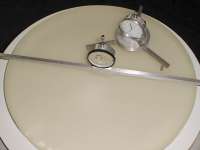
The primary mirror has had the back ground flat and polished. The front surface is hogged to a sagitta of 0.190". The final sagitta will be about 0.340". The curve has not yet reached the edge in all places.
The primary mirror's floatation cell is under construction. Two triangles have been completed, all 18 glue cups are complete and three of the six ball joints are complete. The remaining four triangles are cut to rough size and the three triangle support arms are also cut to rough size.
In addition, three clamping studs have been completed. These will allow for easier machining of the four remaining support triangles and the three support arms. The studs will clamp all four triangles (or arms) together to allow them to be machined simultaneously. This should save some work in the completion of the cell.
The remainder of the optical tube assembly is undergoing conceptual design. The key areas being investigated are the baffle / relay lens tube and the collimation adjustment mechanism which couples the primary's floatation cell to the relay lens tube.
|
Introduction
A relay telescope is one in which the first focal plane in the telescope is buried well inside the scope. The primary has a relatively short radius of curvature while the whole scope enjoys a moderate focal ratio and is quite compact. To understand the concept, imagine a classical Cassegrain telescope with a nearly flat secondary mirror. Normally, Cassegrain systems employ a convex secondary to extend the focal plane far enough to exit the rear of the telescope. In a relay telescope, the first focal point is allowed to fall just a short distance from the (flat or mildly convex) secondary. That focal point is then examined with a second optical system whose object point is the primary's focal point and whose own focal point is beyond the rear of the telescope as in a normal Cassegrain and its variants.
This arrangement has several advantages. The first of which is that it allows for a relatively short, compact telescope with a moderate focal ratio. It allows focal ratios comparable to those of smaller Newtonians -- F/7 to F/8. Because of the compact nature of the system, larger sizes may be designed which would become unwieldy if implemented as a Newtonian. The second major advantage is that they are self baffling. If a field stop is placed at the primary's focal plane, the secondary optical system images only that focal plane. No light may enter the final image area that wasn't first imaged by the primary. This means that a very open structure may designed for the telescope without fear of baffling problems. Finally, because of the presence of the secondary optical system, it is possible to make all surfaces spherical to ease implementation. The added number of spherical lens surfaces makes a good trade off from the deep conic surfaces of a classical Cassegrain.
My first introduction to the concept of relay telescopes was back in April and June 1968 in the form of two articles in Sky and Telescope magazine. In those issues, the well known optical designer Richard Buchroeder presented a design for a telescope which used a series of lenses (7 of them!) to relay the focal plane of a short focus mirror to an observable position. Mr. Buchroeder followed up that original article with a new design in November 1968. The second relay telescope design was simplified, but still used four lenses in the relay system and added a mangin secondary to the system.
The next improvement in relay telescope design came in November and December 1977 when Donald Dilworth described his design for a relay telescope in Sky and Telescope. His design used two lenses in the relay system but also used the mangin secondary as an added element for correction. The complexity of even this design appeared to be great and well out of my reach given the ATM skills I had. I all but forgot about these exotic designs. The concept and excitement were rekindled when I began to plan a telescope around a 17.5" lightweight mirror blank I purchased.
Requirements
The first step in planning this major telescope making project was to decide exactly what I really wanted and how I would be using it. After considerable thought, I came up with these overall requirements.
- 17.5 Inch Aperture
Since I had obtained a 17.5" mirror blank, I wanted to use it for a new telescope project. The blank is 1.375" thick and weighs only about 26 pounds. This seemed ideal for a large aperture highly portable telescope.
- Moderate Focal Ratio -- F/7.0 to F/8.0
I wanted to have a nice all purpose focal ratio for this telescope. While I am more interested in planetary observing than deep sky, I sometimes do both. An F/7 to F/8 optical system seemed to be a good compromise for a general purpose scope. In addition, most of the inexpensive eyepieces I already have probably work best at this intermediate focal ratio.
- Light, Compact and Easily Portable
Much of my observing is done at public star parties. After sharing an evening with the public, I do some further observing on my own. This necessitates an easily portable telescope. In addition to just being portable, I want it to be portable enough to be packed into the trunk of a mid sized automobile. This requires that the unit be able to break down into compact components in addition to being light in weight.
- Easily Accessible Eyepiece Position
Since I am very active in public observing I wanted a low, convenient eyepiece height so observing would not require even a short ladder. In addition, because of my love for planetary observing, an eyepiece height low enough to sit while observing is a great help. It allows me to relax at the eyepiece and wait for those few moments of exceptional seeing.
- Clock Driven Equatorial Mounting
Again, to facilitate public star parties and planetary observing, I require that the telescope be clock driven. An equatorial mount is not a hard requirement, but simplifies the task of designing a clock drive into the mounting. In addition, though not active in imaging now, I want to keep that option open for the future.
With these requirements in mind, I began looking at designs that would work for me. In reading back through my old Sky and Telescope magazines, I again came upon the Buchroeder articles. They got me to thinking about the relay telescope designs again. A message on one of the internet's ATM email lists put me in contact with someone who had built a Dilworth Relay Telescope. His 16" is only the second known to exist. Don Dilworth's original prototype was a 16" also. At the time we started to correspond, I didn't remember the Dilworth design article, but upon rereading it, I decided that this would fit my requirements. I began thinking about the various design aspects and trying to prepare myself for the challenge of executing this complex design.
In the intervening years since Dilworth's original article, he had improved the design somewhat. He added a third lens to the relay system and changed some of the glass types to further improve image aberrations and flatten the field. This newer design would become the basis for my own implementation.
There are a number of aspects of this design that still intimidate me. First, this will be my first large mirror project. The all spherical nature of the design helps, though. Secondly, there are four lenses to make, including the mangin secondary, and I've never done lenses before. This is a new skill I will have to learn as I proceed. Third, the overall tolerances are pretty tight in places and will require careful patience on my part. All of these things are a stretch for my current skills, but I'm forging ahead anyway. This will undoubtedly be an educational experience. I originally allowed myself about two years for this project, but now feel that may be overly optimistic given the time I have been able to put into it so far.
Optical Layout
 At left is a diagram of the optical layout of my Dilworth Relay Telescope. As can be seen, it consists of the primary mirror, the mangin secondary, and the set of three relay / corrector lenses. The focal plane of the primary lies a few inches in front of (to the left of) the first relay lens. I have decided to make the overall system focal ratio F/7.5. At left is a diagram of the optical layout of my Dilworth Relay Telescope. As can be seen, it consists of the primary mirror, the mangin secondary, and the set of three relay / corrector lenses. The focal plane of the primary lies a few inches in front of (to the left of) the first relay lens. I have decided to make the overall system focal ratio F/7.5.
There is plenty of back focal length easing the design of the main optical component cell. The total length of the primary and secondary is about 45 inches. This is only about one third the length of the equivalent Newtonian. The length of the baffle tube in front of the primary is about 18 inches. The field stop is at the front of the baffle tube while the first relay lens is recessed 6 inches farther down the tube. The focal point of the system lies about 19 inches from the back of the primary mirror.
More to come...
|
Optical Design
  These diagrams show the raytrace results of the design. The spot diagrams compare favorably with a Newtonian of the same physical size. These diagrams show the raytrace results of the design. The spot diagrams compare favorably with a Newtonian of the same physical size.
More to come...
|
Optical Tube Assembly
More to come...
|
Mirror Cell Design
 Much time has gone into the design and fabrication of the primary mirror's cell. Since I have set out a possible requirement for an equatorial mounting, the Dobsonian methods of simple cell and sling would not work for me. In an equatorial mounting, there is no constant "bottom" to the mirror cell. Any portion of the mirror may find itself on the bottom at any given time depending on where the telescope is pointed. My thin mirror complicates the job of good support in all positions.
I decided to use an 18 point floatation cell, but glue the mirror to the cell rather than design an equatorial compatible sling support for the edge. The glue I intend to use is RTV (GE Silicone II.) This is a proven stress-free means of attaching glass optics to other objects. Each of the 18 contact points of the floatation cell is replaced with a small cup to hold the RTV in position while it cures. The thickness of the RTV above the edge of the cup is governed by a small nylon screw adjacent to the cup. When I am ready to attach the mirror to its cell, I will install the 18 nylon screws and then fill each glue cup with RTV. A small crown of RTV will be allowed over each cup so that when the mirror is placed on top of this assembly, the RTV may spread to about 0.5 inch diameter. After the RTV has thoroughly cured, the nylon screws will be removed leaving each contact point attached to the mirror with a uniform thickness of RTV.
I was at first concerned with stressing the thin mirror by gluing it to the cell. A few quick calculations of the difference in CTE (coefficient of thermal expansion) between the glass and the aluminum of the cell showed little problem. A quick test of the resiliency of the RTV showed the opposite problem -- it is almost too rubbery and will allow the mirror to sag slightly when pointed near the horizon. For this reason, I decided to make the RTV rather thin. It will be only 0.050 inches thick.
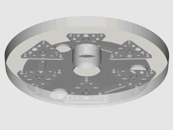
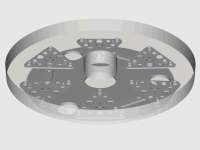
A key design attribute of the cell is that it must be strong and light in order to meet my goals of easy portability. I chose aluminum for all the major components of the cell. In many cases, the aluminum components may appear to be a bit thin given conventional design recommendations, but the RTV attachment of the mirror will allow for a small amount of bending of the components without appreciable added stress. Even when slightly bent, each component will continue to support an equal weight of the mirror -- the cell's primary purpose. In addition, the individual parts are made as light and open as possible. The holes and open nature of the cell are required to facilitate rapid forced air cooling of the mirror. There will be three small 2 inch diameter (CPU Cooler type) fans installed in the rear section of the optical tube assembly for this purpose. I want to allow for as much free flow of air around the back of the mirror as possible. A brief description of each of the cell's components follows.
|
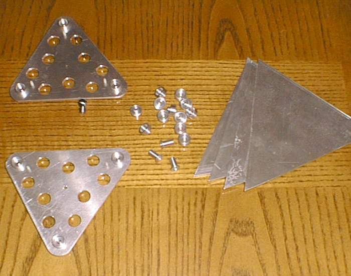
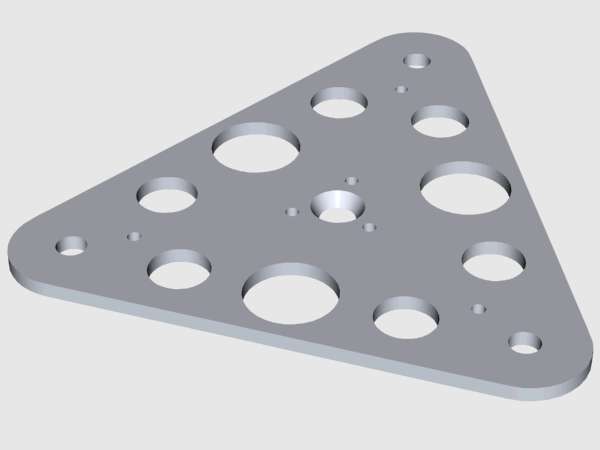
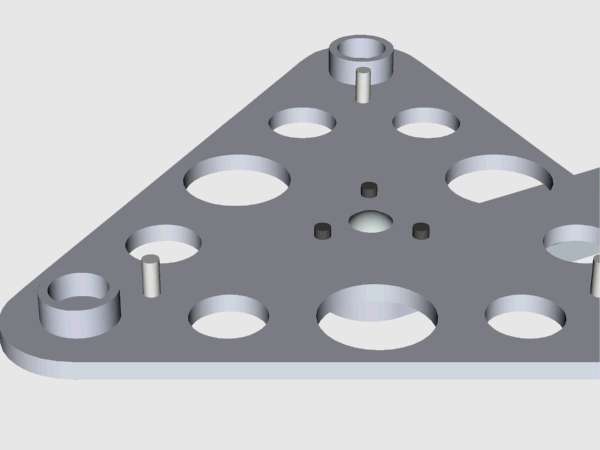
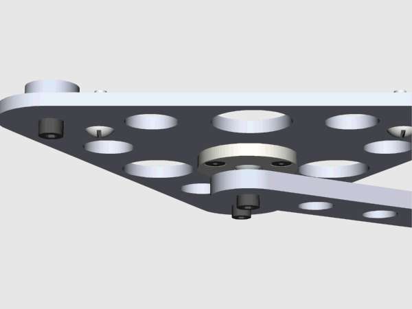
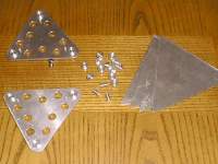
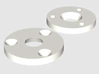
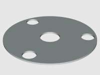
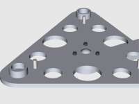
 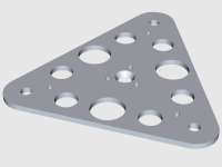 Here, the floatation cell support triangles are shown. Each of the six triangles is made from 0.125 inch thick aluminum plate. Holes are drilled wherever possible to aid air flow for cooling. The placement of the holes is arranged so that there is still a direct path of (nearly) uninterrupted metal between the central support point and the glue cup support points at the corners of the triangles. The central support point of the triangle is countersunk and will become one half of the receptacle for the ball joint the triangle rests on. This ball joint will allow the triangle to pivot and position itself so that each corner accepts an equal weight of the mirror. The 4-40 NC threaded holes near each glue cup mounting hole are for the attachment of the nylon assembly spacing screws mentioned above. The screws will be removed following final assembly of the mirror and cell.
|
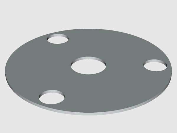
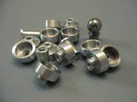
 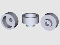 At left are drawings of the individual glue cups. These are attached to each corner of each triangle using 6-32 NC machine screws and washers. This construction will allow me to disassemble the cell if required for any reason. The glue cup may remain glued to the mirror while the rest of the cell is removed. This should also make it much easier to remove the RTV and glue cups for mirror recoating or other reason. Each glued contact point will be easily accessible for cutting of the RTV after removal of the support triangles. These glue cups are 0.5 inch outside diameter. When glued to the mirror's back with RTV, they will provide a relatively thick cushion for the mirror in the vertical direction but a relatively tight hold laterally. This allows for something of a soft support when viewing at the zenith and a firmer support when pointed toward the horizon. (I am hoping that this will be sufficient to keep the mirror from sagging on its cell since centering is rather critical with this optical arrangement.
|
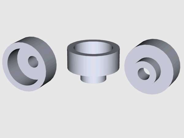
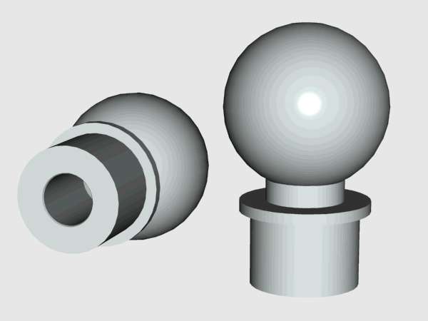
 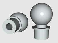 Each ball joint is made up of two pieces which are then brazed together. The bottom section is made of steel and acts as a holder and attachment means for the ball portion of the joint. The ball portion is simply a 0.375 inch diameter ball bearing. The two parts are attached with a strong silver brazing solder. ( I am using type BAg-1, also known as Silvaloy 45 or Easyflow 45.) The actual attachment point of the brazed joint is the inside of the hole drilled through the support section. This results in a very strong attachment which is invisible from the outside. It also results in most of the ball being accessible and smooth for best working of the joint.
|
  Here, the ball joint lower clamp is shown. This part is made of teflon, though aluminum would also work well since the ball joint will not actually see any appreciable movement. These clamps are screwed to the triangles with three 4-40 NC countersunk socket screws. A small drop of Loctite compound will be used to keep the screws from loosening once installed. This part with its countersunk recess and the triangle's countersunk recess trap the ball portion of the ball joint while allowing a pivoting motion in any direction (for short movements.) This part is plug drilled from 0.125 inch thick teflon plate and then drilled and machined to final shape.
Since each triangle will be glued to the mirror via the glue cups, there will not be a need for anything to constrain the rotaional motion of the ball joints. I intend to make a plastic ring or other fixture to hold the triangles in the correct orientation while gluing, then remove it after the RTV has cured. The ball jonts will allow the mirror to find its own level but do not constrain the motion in any other direction.
|
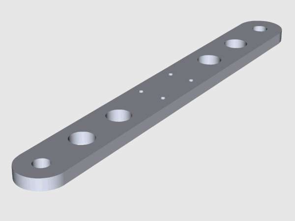
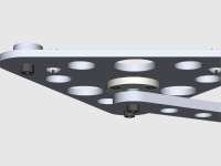
 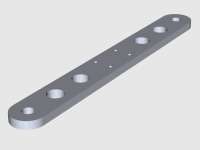 This part is one of three support arms for the cell. Each arm holds two triangles -- one on each end. The holes at the ends of the arms accept the mounting section of the ball joints. The ball joints are attached with 6-32 NC machine screws and washers. The arm is machined from 0.1875 inch thick aluminum plate. A minimum number and size of air circulation holes were allowed in this part so that bending would be kept to a manageable amount. A constrained pivoting bracket is attached at the center of each arm.
|
 
|
 
|
|
|
Mounting Design
The mounting design has not yet begun.
|
Optical Construction
The primary mirror is under construction now. Details will be provided soon.
|
Mirror Cell Construction
The mirror cell is under construction now. Details will be provided soon.
|
Optical Tube Assembly Construction
Construction of the optical tube assembly has not yet begun.
|
Mounting Construction
Construction of the mounting has not yet begun.
|
John D. Upton
Last Page Update: Sunday, 15-August-1999
Page Contents Copyright © 1998-1999, John D. Upton