
Figure 1: ATM Cell Format
1. INTRODUCTION
Networks are highways, with many similar characteristics and tradeoffs. Flexibility, conformance to standards, efficiency, ease of use, security, control, management, cost, and overall performance, to mention a few. Balancing and controlling them end to end will be crucial in building a successful network infrastructure.
Choosing the right technology for networks carefully is critical, since as organizations move toward the network-computing model, network infrastructures will become your key competitive advantage. You must therefore choose a technology that meets these new challenges and performs seamlessly from the backbone to the desktop. This choice is not always easy, as there are a number of competing technologies available that seem to meet the challenges of these new networks, including Asynchronous Transfer Mode (ATM) and switched Ethernet technologies such as Fast Ethernet and Gigabit Ethernet.
ATM has proven to be the backbone of choice for future high-performance networks.
Delivering high-quality applications is how networks will be judged. Does it handle all the delivery requirements of current and future users? Does the architecture allow for multimedia applications? Can voice, full-motion video, imaging, as well as high-priority data applications are accommodated on the same network effectively? Has the network been architected from the "frame" out to support these applications, and is this frame based on industry standards?
It's not all about raw speed. Control, flexibility, adaptability, cost, and manageability are all significant aspects. Balance is an essential aspect in the overall performance of any networked system. Matching the technology with the user's requirements and applications will be the challenge. ATM's scalability coupled with IBM's Switched Virtual Networking will allow you to match the application needs of all of your end users with the best-fit technology across a common architecture. It has the robust architecture, management, and ease of use. It also has the best scalability, meaning it offers you the most flexibility to adapt to changing conditions in the same standard technology.
Through the efforts of the ATM Forum, ATM is capable of transferring voice, video, and data through private networks and across public networks. ATM continues to evolve today as the various standards groups finalize specifications that allow interoperability among the equipment produced by vendors in the public and private networking industries.
Data at high speeds are segmented into units called cells. Each cell is of 53 octet long consisting of a 5 octet header and 48 octet of payload data, as shown in Figure-1.
Cells transit ATM networks by passing through devices known as ATM switches, which analyze information in the header to switch the cell to the output interface that connects the switch to the next appropriate switch as the cell works its way to its destination.
ATM is a cell-switching and multiplexing technology that combines the benefits of circuit switching (constant transmission delay and guaranteed capacity) with those of packet switching (flexibility and efficiency for intermittent traffic). Like X.25 and Frame Relay, ATM defines the interface between the user equipment (such was workstations and routers) and the network (referred to as the User-Network Interface, or UNI). This definition supports the use of ATM switches (and ATM switching techniques) within both public and private networks.
Because it is an asynchronous mechanism, ATM differs from synchronous transfer mode methods, where time-division multiplexing (TDM) techniques are employed to pre-assign users to time slots. ATM time slots are made available on demand, with information identifying the source of the transmission contained in the header of each ATM cell. TDM is inefficient relative to ATM because if a station has nothing to transmit when its time slot comes up, that time slot is wasted. The converse situation, where one station has lots of information to transmit, is also less efficient. In this case, that station can only transmit when its turn comes up, even though all the other time slots are empty. With ATM, a station can send cells whenever necessary.
Contrasts TDM and ATM multiplexing techniques.

Figure 2: TDM and ATM
Multiplexing Techniques
Another critical ATM design characteristic is its star topology. The ATM switch acts as a hub in the ATM network, with all devices attached directly. This provides all the traditional benefits of star-topology networks, including easier troubleshooting and support for network configuration changes and additions.
*Furthermore, ATM's switching fabric provides very high bandwidth. As long as the switch can handle the aggregate cell transfer rate, additional connections to the switch can be made. The total bandwidth of the system increases accordingly.
The UNI specification defines communications between ATM end-stations
(such as workstations and routers) and ATM switches in private ATM networks.
The format of the UNI cell header is shown in Figure-3.
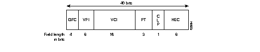
Figure 3: UNI Header
Format
The UNI header consists of the following fields:

The GFC field is not present in the format of the NNI header. Instead, the VPI field occupies the first 12 bits, which allows ATM switches to assign larger VPI values. With that exception, the format of the NNI header is identical to the format of the UNI header.
Figure-5 is a reference model that illustrates the organization of ATM functionality and the interrelationships between the layers of functionality.

Figure 5: ATM Reference Model
In the ATM reference model, the ATM layer and the ATM adaptation layers are roughly analogous parts of the data link layer of the Open System Interconnection (OSI) reference model, and the ATM physical layer is analogous to the physical layer of the OSI reference model. The control plane is responsible for generating and managing signaling requests. The user plane is responsible for managing the transfer of data. Above the ATM adaptation layer are higher-layer protocols representing traditional transports and applications.
The ATM physical layer is divided into two parts: the physical medium sub-layer and the transmission convergence sub-layer. The physical medium sub-layer is responsible for sending and receiving a continuous flow of bits with associated timing information to synchronize transmission and reception. Because it includes only physical-medium-dependent functions, its specification depends on the physical medium used.
ATM can use any physical medium capable of carrying ATM cells. Some existing standards that can carry ATM cells are SONET (Synchronous Optical Network), 100-Mbps local fiber (Fiber Distributed Data Interface [FDDI] physical layer), and 155-Mbps local fiber (Fiber Channel physical layer). Various proposals for use over twisted-pair wire are also under consideration.
The transmission convergence sub-layer is responsible for the following:
Table-1 summarizes the characteristics of each AAL.
| Characteristics | AAL1 | AAL3/4 | AAL4 | AAL5 |
| Requires timing between source and destination | Yes | No | No | No |
| Data rate | Constant | Variable | Variable | Variable |
| Connection mode | Connection-oriented | Connection-oriented | Connectionless | Connection-oriented |
| Traffic types | Voice and circuit emulation | Data | Data | Data |
Table 15-1: ATM Adaptation Layers
The main function of an ATM switch is to receive
cells on a port and switch those cells to the proper output port based
on the VPI and VCI values of the cell. This switching is dictated by a
switching table that maps input ports to output ports based on the values
of the VPI and VCI fields, as show in Figure-6.

Figure 6: Maintenance of Virtual Connections
through an ATM Switch
Say, for example, that two cells arrive on port 1 of the ATM switch in as shown in Figure-6. First, the switch examines the VPI and VCI fields of cell 1 and finds that the fields have a value of 6 and 4, respectively. The switch examines the switch table to determine on which port it should send the cell. It finds that when it receives a VPI of 6 and a VCI of 4 on port 1, it should send the cell on port 3 with a VPI of 2 and a VCI of 9. So, for cell 1, the switch changes the VPI to 2 and the VCI to 9 and sends the cell out on port 3.
Next, the switch examines cell 2, which has a VPI of 1 and a VCI of 8. The table directs the switch to send out on port 2 cells received on port 1 that have a VPI of 1 and a VCI of 8, respectively, and to change the VPI and VCI to 4 and 5, respectively.
Conversely, when a cell with a VPI and VCI of 2 and 9, respectively, comes in on port 3, the table directs the switch to send the cell out on port 1 with a VPI and VCI of 6 and 4, respectively. When a cell with a VPI and VCI of 4 and 5, respectively, comes in on port 2, the table directs the switch to send the cell out on port 1 with a VPI and VCI of 1 and 8, respectively. Note that VPI and VCI values are significant only to the local interface.
Figure-7 shows how the VPI field is used to group virtual channels (identified by their VCI values) into logical groups. By reducing the number of fields that have to be changed as each cell passes through the switch, the performance of the switch increases.

Figure 7: Virtual Paths Form Logical Groups
of Virtual Channels
In Figure-7, cells that enter the ATM switch
on port 1 and have a VPI value of 4 are processed through the "VP switch,"
which changes the VPI value of each cell to 5, but leaves the VCI value
intact, and sends the cell out on port 3. Cells that have a VPI value of
1 are processed through the "VC switch." For cells that have a VCI value
of 1, the VC switch changes the VPI to 4 and the VCI to 4 and sends the
cell out on port 2. For cells that have a VCI value of 2, the VC switch
changes the VPI to 3 and the VCI to 3 and sends the cell out on port 3.
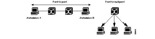
A multicast server
is one solution to this problem. A multicast server can exist in an ATM
network, and all members of a multicast group can establish point-to-point
VCCs to it. The multicast server would then create a point-to-multipoint
VCC to all members on the group, with itself the root, as shown in Figure-9.

Figure 9: Multicast server.
Any data sent to the multicast server is serialized, sent out the point-to-multipoint tree, and received by the members of the group. The value of this approach is that cells from different sources are serialized and sent in order rather than interleaved. The multicast server can also support dynamic groups because members can be added and deleted as leaves on the tree.
Advantages of ATM PVC service include a direct ATM connection between routers and the simplicity of the specification and subsequent implementation. Disadvantages include static connectivity and the administrative overhead of provisioning virtual connections manually.
It is the responsibility of the ATM device to adhere to the contract by means of traffic shaping. Traffic shaping is the use of queues to constrain data bursts, limit peak data rate, and smooth jitter so that the traffic will fit within the promised envelope.
ATM switches have the option of using traffic policing to enforce the contract. The switch can measure the actual traffic flow and compare it against the agreed upon traffic envelope. If it finds that traffic is outside of the agreed upon parameters, the switch can set the CLP bit of the offending cells. Setting the CLP bit makes the cell discard eligible, which means that the switch, or any other switch handling the cell, is allowed to drop the cell during periods of congestion.
Congestion control is a primary concern of ATM designers. For example, dropping just one cell that is part of a FDDI frame can result in the retransmission of 93 cells.
Retransmission can lead to an exponential increase in congestion as ATM switches drop individual cells from different packets, resulting in retransmission of more packets, which causes even more cells to be dropped.

The signaling packet is reassembled by the switch and examined. If the switch has a switch table entry for Router B's ATM address, and it can accommodate the QOS requested for the connection, it sets up the virtual connection on the input link and forwards the request out the interface specified in the switching table for the ATM NSAP of Router B.
Every switch along the path to the endpoint reassembles and examines the signaling packet and forwards it to the next switch if the QOS parameters can be supported while setting up the virtual connection as the signaling packet is forwarded. If any switch along the path cannot accommodate the requested QOS parameters, the request is rejected, and a rejection message is sent back to the originator of the request.
When the signaling packet arrives at the
endpoint (Router B), it is reassembled and evaluated. If the endpoint can
support the desired QOS, it responds with an accept message. As the accept
message propagates back to the originator of the request, the switches
set up a virtual circuit. The originator of the request receives the accept
message from its directly connected ATM switch, as well as the VPI/VCI
value that the originator should use for cells destined for the endpoint.
10. Applications
The picture below shows probable service categories
for ATM applications 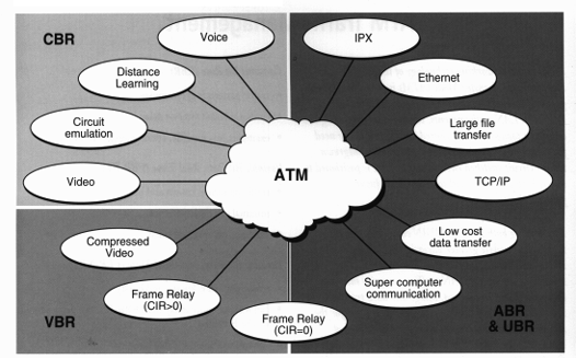
Figure 8 ATM Applications.
11. Conclusion
Telecommunications networks have come a long way in the last couple of decades. What used to be decisively different networks are now coming together in a reformation of telecommunications topologies and architectures. This change is being driven by the ultimate goal of integrating voice, video, and data all into one giant multimedia network. ATM is the current technology that will take us further on this quest for integration. Fast Ethernet is currently a bargain as far as price for bandwidth, but in the future ATM has the tools to make it the obvious choice for multimedia. ATM's price will eventually come down and should be able to compete with Fast Ethernet in the LAN market.
The authors of this paper thank Dr. M. S. Shiva kumar, Head, Department of Computer Science & Engineering and Mr. K. Raghuveer, Lecturer, Department of Computer Science & Engineering of The National Institute of Engineering, Mysore for Their valuable guidance in writing this paper.