|
BRITISH ARTILLERY FIRE CONTROL |
|
Updated 10 May 2014 |
|
|
|
|
|
CONTENTS |
|
|
|
|
|
|
|
|
|
|
|
|
|
|
|
|
|
|
|
|
|
|
|
|
|
| UNIFICATION | |
|
|
This page describes how British guns were oriented and layed to deliver indirect fire in the 20th Century. Indirect fire means the guns have to be aimed without being able to see their target. Aiming means pointing the guns in the required azimuth and with the required elevation angle in the vertical plane. Sighting arrangements for this underpin indirect artillery fire. The production of firing data that is applied to the sights is described on other pages.
Unfortunately many of the guns on display in museums lack complete sights so it’s often difficult to see how they worked. Sometimes some elements are present, in others everything has ‘disappeared’. Moreover, even when sights are displayed they are usually those in use when the gun left service, the sights first used with a gun, particularly for early guns, are seldom if ever shown.
The first issue is what to aim at. With direct fire the No 1 of each gun selected his target as ordered and engaged it. Sometimes all guns aimed at the same point, such as when trying to breach fortress walls. In other situations they aimed at different points or parts of the target. In practice the battery commander (BC) sometimes aimed guns himself, and during the 19th Century it was also quite common for the section commanders (subaltern officers) to initially lay the two guns in their section themselves to ensure that the layers knew the correct target.
Indirect fire required a different approach. It clearly wasn’t practical to aim simultaneously at individual elements in the target area, which had been the custom with direct fire. There were two options, either:
In essence the second approach was adopted, although it’s not clear if the choice was ever discussed, and with it acceptance, if not recognition, that the indirect firing battery was primarily an area weapon. Of course this approach involved a further choices. Should the guns be aimed to cover a particular size area, either a default size or as required for the target? Or should they merely fire with barrels parallel so that the fall of shot reflected the layout of the battery, which was usually a straight line?
Speed and simplicity was a key consideration and probably drove the decision. The result was that until the 1980's the guns of a battery normally fired with their barrels parallel to one another and with the same range set on their sights. During WW1 and onwards this range was corrected for muzzle velocity (MV) and other variations.
Until into WW2 the battery layout was normally a straight line, alternatives were rarely considered. Although in WW1 it was not unusual for siege or heavy batteries to deploy in section positions a hundred yards or more apart and not in a battery line. Sometimes in WW1 field batteries also deployed in a ‘ragged’ line to make use of opportunities for concealment. However, battery layout was formalised between the wars to be a straight line at right angles to the zero line. The gun at the right end of the line, looking in the direction of the target, was the ‘pivot’ gun and battery firing data was calculated from its position.
Curved gun lines were introduced in WW2 because they gave better direct fire against tank attacks from a flank. Then, when the war moved away from deserts the need for concealment re-asserted itself and battery layouts were fitted to the terrain features to maximise opportunities for concealment and camouflage. By the end of the war, with the threat of air or tank attack mostly an unhappy memory, straight lines often re-asserted themselves because they were simpler to cope with.
However, throughout WW2 and afterwards the required fall of shot on the ground, with barrels parallel, was for gun aimpoints to be roughly straight at right angles to the line of fire. If individual guns were not positioned in a straight line they were ordered position corrections to get their fall of shot to represent a roughly straight line battery. These corrections were also used if the line of guns was at a right angle to the zero line and the line of fire was at a substantial angle from the zero line.
Nevertheless, while parallel barrels were the norm there were other options. It’s useful to remember that before WW1 shrapnel was the standard ammunition, and that the effective width of the shrapnel frontage was 1½ times the battery frontage. However, shortly before WW1 the effective shrapnel frontage was redefined as being the same as the battery frontage.
From the beginning guns’ fire could be aimed to spread out or ‘focus’ on a single point if the tactical situation required it. This was called ‘distribute’ or ‘concentrate’. In a barrage the battery’s fire had to be along a barrage line the width of its ‘battery lane’. The barrage line would seldom if ever be at right angles to the line of fire and the guns’ aimpoints had to be equally distributed across the lane’s width. The result was that each gun had its own range and horizontal angle.
Firing along a line with a required orientation was not, of course, limited to barrages. In WW2 the standard 525 yard Stonk was introduced, replaced in the 1950's by the ‘linear’ of variable length. Just before WW2 base ejection smoke was first issued, this could cover a much greater frontage than HE or WP, although the actual length depended on the wind speed and direction, so ‘deliberate smoke’ shoots had an extended distance between individual gun aiming points, and their layout had to be aligned for optimum effect, see Smoke Screens.
Finally there was ‘sweep and search’, introduced before WW1 it lasted until the international procedures were introduced in 1965. ‘Sweep’ meant changing direction between rounds, ‘search’ meant changing range. They could be used in combination or separately. Either or both could be ordered in the form ‘sweep 200 by 50’, which meant guns were to move their aim up to 200 yards left and right in increments of 50 yards. Since it was for area effect British practice was to use handwheel turns and not precise angles on the sights. With shrapnel, the effective sweep frontage of a battery was 4½ times battery frontage, reduced to 3½ shortly before 1914.
Broadly, if guns fire with their barrels parallel, then their fall of shot will reflect the layout of the guns on the battery position. As already described straight line gun positions were the norm for much of the first half of the 20th century and lasted until the late 1950's when the two troop (8 gun) battery was replaced by 6 guns. This introduced battery centre instead of the pivot gun as the basis for the battery’s firing data and with it the inverted double chevron layout for the guns. This gave depth and a more circular pattern to a battery’s fall of shot when guns fired parallel at the same range. Of course the terrain often dictated something else, for example a gun line along the edge of a wood.
The arrival of electronic computers made other options practical in terms of the time it took calculate different data for each gun. This eventually led to the adoption of standard layout patterns or ‘sheafs’, rectangular and circular, for the fall of shot that could be applied to target areas of different sizes and different numbers of guns. These layouts gave good distribution of individual gun aimpoints across a target area. It also freed gun positions from limits on dispersion or concentration of their layouts, it meant they could deploy tactically according to the situation. However, sheaf sizes (apart from linears) were not available with the first electronic computer FACE. The most modern fire control computers have moved from fixed sheafs to algorithmically derived aimpoints to give optimal coverage of the target area.
The elevation angle is the vertical angle of the barrel needed to deliver a shell to a particular distance with a particular propelling charge. Laying in elevation is a matter of aligning the barrel in the requisite angle from the horizontal plane (tangent) of the earth’s surface. The plane or tangent of the earth’s surface is ‘fixed’, it’s what’s ‘found’ by a spirit level, or in the other axis by a plumb-bob. A standard artillery coloured bubble spirit "level" for all British sights and instruments was introduced in 1912 to replace an earlier assortment.
|
Units of Measurement The British used degrees (circle/360) and minutes for angular measurement and yards for distance until NATO standardisation on metres and mils in the 1950's. Sights were normally graduated to 5 minutes. Degrees have a long history, probably back to Babylonian times where the sexagesimal (base60) number system was used. Degrees are divided in 60 minutes and each into 60 seconds. |
The elevation scale could be graduated in angular dimensions or distance, in which case it was usually called a range scale. Range scales that could incorporate muzzle velocity variation from standard were called 'calibrating'.
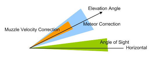
An elevation angle has two components:
The sum of the TE and AoS is called the Quadrant Elevation (QE). The TE corresponds to the horizontal range, corrected for non-standard meteor conditions and MV. The Range or Firing Table (RT or FT) lists TE for every 100 yards or metres of range, although at some periods RTs gave the angle of projection. Figure 1 shows the main elements of QE, see ballistic angles for more details.
Figure 1 - Main Components of QE
Corrections for MV and meteor started being applied in WW1.
A clinometer, under various names, was used to align a gun in its required elevation angle. By the end of the direct fire era in the late 19th Century clinometers, sometimes called a 'gunner's level', were generally of the Watkin type. These were set by screwing a drum marked with elevation angles up or down, this was attached to the leveling bubble holder and so changed its angle relative to the clinometer's plane. However, the Sighting Telescope Mk 6 used with 15-pr had an integral clinometer. More usually clinometers were placed on top of the sighting telescope when laying in elevation.
Figure 2 - Watkin Type Clinometer
Click the picture
to see it enlarged
In the 19th Century tangent sights were used for direct fire, in essence they were large rifle sights. They comprised a 'acorn' shaped foresight and a 'notched' backsight mounted on the ordnance on its left or right side. The backsight, mounted in a bracket attached to the breech, could be raised or lowered to set the range. The scale beneath it was graduated in yards, a longer range being further down the scale so that the barrel had to be elevated for the fore and backsights to be aligned on the target. Different propelling charges had different scales as did different guns and howitzers. The adoption of QF guns meant that these sights could be moved onto the cradle. However, the non-recoiling cradle offered other solutions.
Figure 3 - Tangent Backsights
Click the picture to see it enlarged
|
|
The first was the use of bar sights where the fore and backsights were mounted at either end of a short bar fixed to the cradle. It could mount a telescope as well as an open sight, previously telescopes had been mounted on the trunnion. It functioned in the same way as the tangent sight except that on some guns the scale was curved and faced to the side, on others it was a drum.
Figure 4 - Bar Sight
Side and rear views of 'Sight, Bar, Carriage, Field, QF 4.5-inch Howitzer Mark 1'
Click the picture to see it enlarged
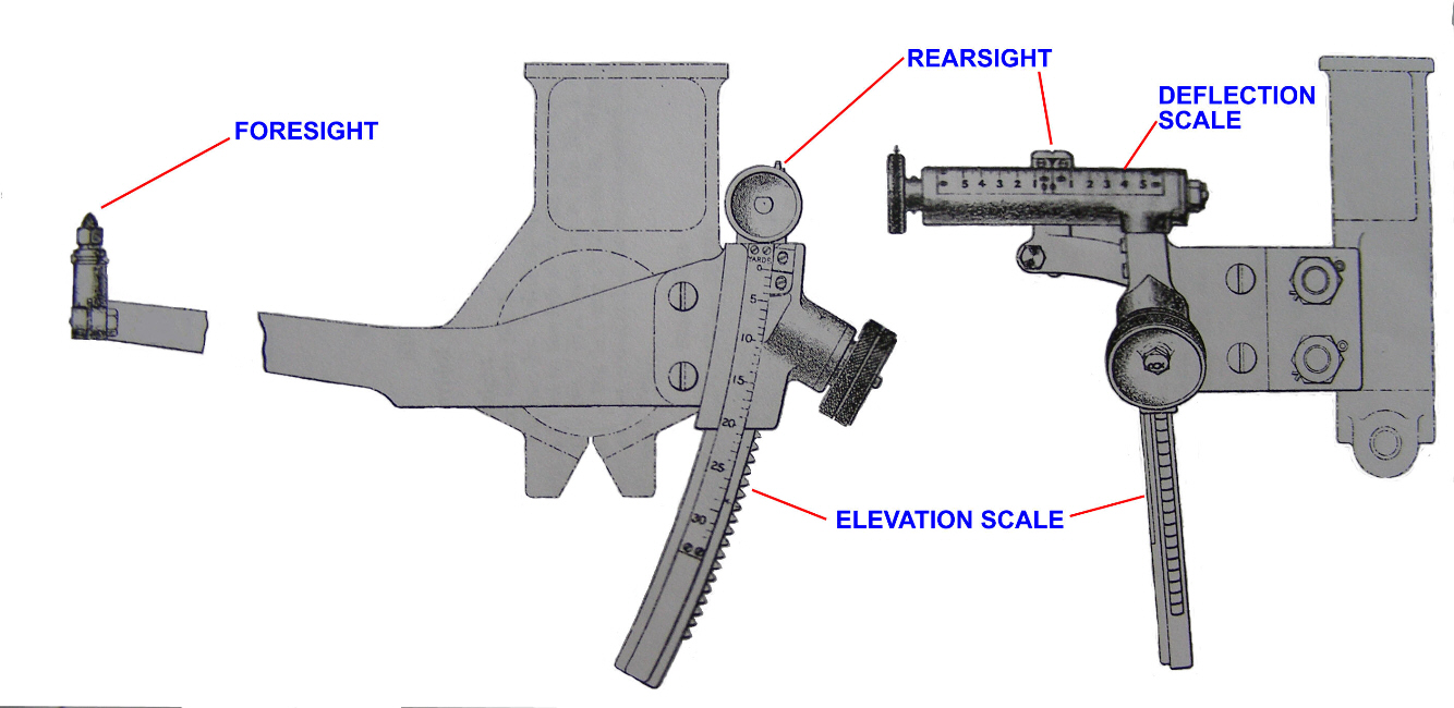
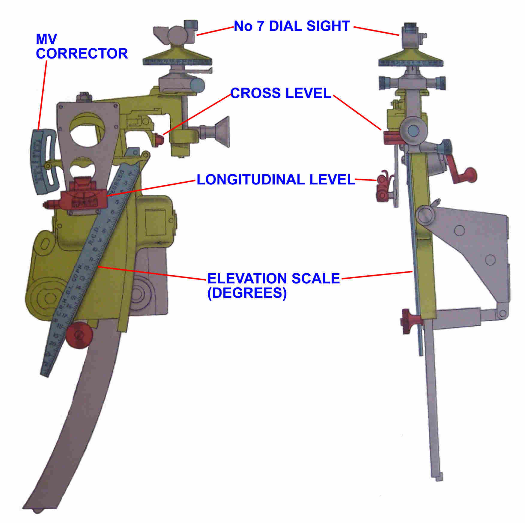
Introduction of the 60-pdr Gun highlighted the problem of wheels at different heights, 'trunnion tilt', when the gun was across a slope. This meant that the shell did not go where it was aimed by the sight, the relatively long range of the 60-pdr exacerbated the problem. The traditional solution was to calculate a horizontal deflection angle to correct for this tilt. The better solution was oscillating (soon called reciprocating) sights. These meant the sight could be cross-leveled when the trunnions were tilted. Various arrangements were tried but an oscillating sight was introduced for the 60-pdr in about 1910, just before the optical No 7 Dial Sight entered service to replace the open sight No 1 Dial Sight that did use a sight mount. This oscillating sight had a range drum graduated in both yards and degrees, and it still had a telescope mount and a precision deflection scale. These mounts also saw the introduction of a new style of clinometer, see Figure 8 below, sometimes called a 'longitudinal level'.
Figure 5 - Oscillating Sight
Side and rear views of 'Sight, Oscillating, BL 60-pdr, Mark I* and II'
Click the picture to see it enlarged
The next advance was the development, Independent Line of Sight using a Rocking Bar. This enabled the elevation sights and barrel to be moved together or separately, with tangent and simple bar sights they could only be moved together. In 1910 'modern' dial sights (described in the next section) were introduced and the combined elevation and azimuth sighting arrangements were changed. The new arrangements separated the general purpose dial sight from the gun-specific dial sight carrier. The dial sight itself was not part of the sight mount. The mount was oscillating but retained a telescope and deflection scale.
Figure 6 - Rocking Bar Sight
Side and rear views of 'Sight, Rocking Bar, 6-inch Howitzer, Carriage Mk III' (30 cwt)
Click the picture to see it enlarged
With the introduction of optical dials sights in 1910 the sight mount soon became a 'Carrier, Dial Sight No 7' (Dial Sight No 7 was the designation of the first optical dial sight that lasted into WW2). This was typically an elevation or range ‘scale’ (variously called -scale, -drum, -dial, -indicator) and the primary scales were graduated in yards. Range drums were similar to those used with Watkin type clinometers but larger. This change meant that elevation was ordered to the guns in yards unless ‘clinometer laying’ was being used, see below. The first of the new dial sight carriers was for the 4.5-inch Howitzer. Being a howitzer meant that it had several different charges.
Figure 7 - Dial Sight Carrier
Side and rear views of 'Carrier, No 7 Dial Sight, No 1 Mark 1' (4.5-inch Howitzer)
Click the picture to see it enlarged
Range scales were simple for true guns with their single propellant charge. Howitzers with several charges were more complicated. The solution for the 4.5-inch Howitzer was a range drum for charge 4 and a separate scale that enabled ranges at other charges to be converted to a charge 4 range. Probably the first use of what soon became known as a 'false range'. Of course a false range across different charges had an inherent problem; as guns wore their MVs changed but the amount of change was neither the same for all charges nor always exactly proportional.
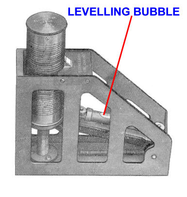
However, range scales graduated in yards didn't cope with an Angle of Sight, which was common to all guns in a battery. The solution was the sight clinometer. This functioned as the elevation leveling bubble, and had the Angle of Sight set on it as an ‘offset’ to the TE. The range drum and sight clinometer were physically part of the sight ‘carrier’. The mechanical linkages were such that when the range and Angle of Sight were set and the barrel elevated until the sight clinometer leveling bubble showed level, then the barrel was in the required QE.
Figure 8 - Clinometer, Sight , Mark 1
Side view
Click the picture to see it enlarged
This simplicity of a range scale worked well until calibration was adopted by field artillery in WW1 and guns started having different MVs due to their varied wear. A MV different to standard affected the relationship between range and elevation angle. One partial solution was to group guns in batteries according to their MV, ideally with all guns in the battery having MVs that were close enough to be treated as the same. It was important because if differing MVs were not corrected then the fall of shot from a battery would be more spread out than was desirable – the guns did not ‘shoot together’.
Differences in guns’ MVs had to be accommodated and there were two possible approaches. Either the battery staff did it for all guns in the battery, given to each gun as an individual range correction or each gun determined its own. The speed benefits of each gun doing its own, ‘parallel processing’, were obvious - rounds on the ground quicker. Obviously guns doing their own calculations wasn't a good idea, and if it produced a range correction this still had to be added to the range ordered.
The initial approach was to convert a gun’s MV difference from standard into ‘gun corrections’ in yards, these were applied by the gun No 1 to the ordered range. Each gun was given a ‘registration card’ that provided the gun correction for different ranges, charges and propellant types. However, it seems that sometimes the ‘zero’ of the TE scale on the sight was adjusted to reflect the gun correction. This, of course, was only possible with ‘true’ guns having a single charge and it wasn’t ideal because the size of the range variation of MV is not linearly proportional to range. It also appears that some guns had ‘correction rules’ (later called 'gun rules') to adjust the range for their MV. In some true guns, notably the 60-pdr pre WW1, the range scale could be correctly offset for the actual variation in MV. All this pointed to the way ahead.
The UK solution to the problem was ‘calibrating sights’ that could be used with multi-charge guns. In effect this meant that the relationship between a gun’s range scale and actual elevation angle could be adjusted ('calibrated') to reflect its MV. It meant that all guns in a battery could be ordered the same range, which was set on their calibrating sight, but each could have a different elevation angle depending on their MV. It eliminated a source of possible arithmetical mistakes as well as enhancing the speed advantages of ordering a single range to the battery. It also gave a tighter fall of shot for a battery than using a single mean MV when there was a wide spread of MVs.
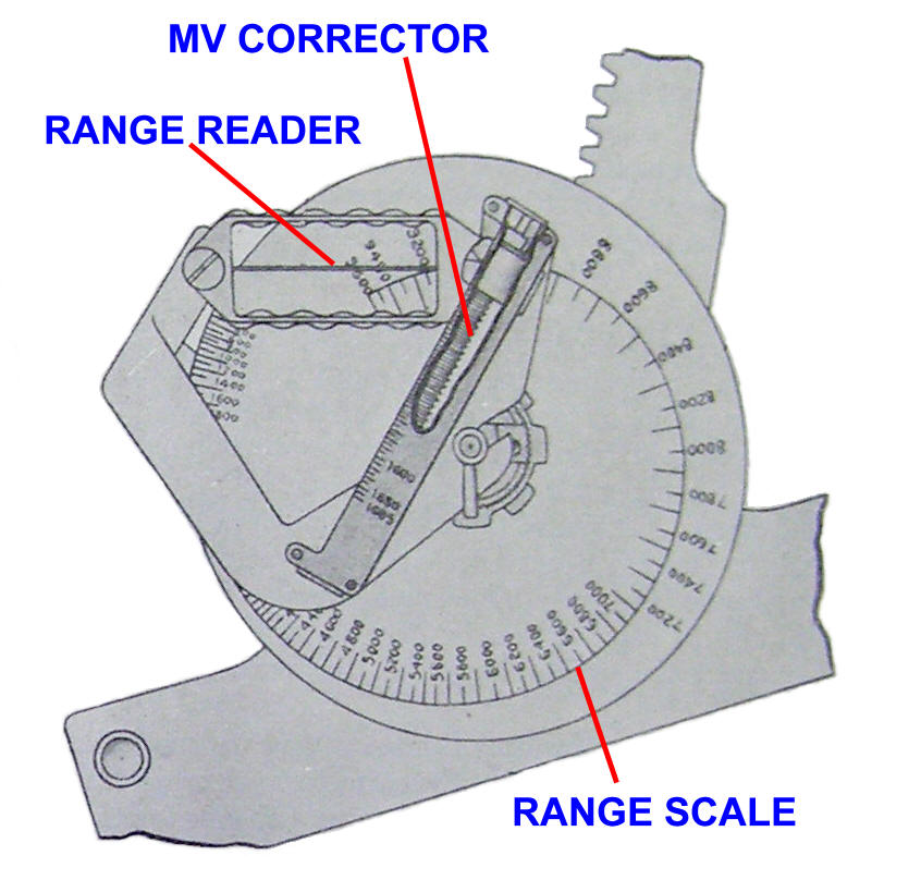
Calibrating sights started appearing before WW1. The first was probably the 60-pdr (used by the Royal Garrison Artillery). This used a new type of sight carrier sight carrier that had a MV corrector that offset the range scale reader. .
Figure 8 - Calibrating Sight
Side and rear views of 'Carrier, No 7 Dial Sight, No 6, Mark I*' (60-pdr)
Click the picture to see it enlarged
However, another pattern was a circular range indicator on the right side of the gun and connected to the elevating arc. 18-pdr used this, which required 2 man laying because the dial sight was on the left.
Figure 9 - Range Indicator for 18-pdr
Click the picture to see it enlarged
Of course in practice not even guns were 'single charge', they had full and reduced charges and during WW1 new shell models were introduced that had different ballistic characteristics and hence different MVs. The solution to this was exchangeable range scale plates. Of course this meant a new sight carrier that enabled easily changed range scales.
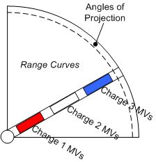
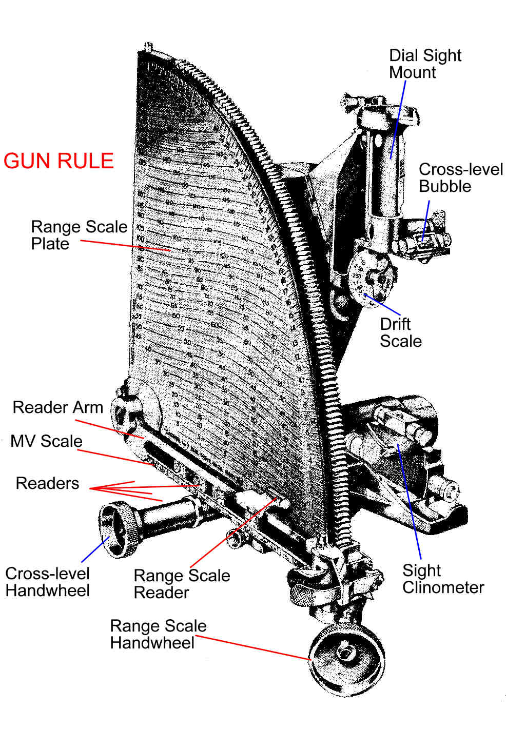
Calibrating sights became the norm and in about 1930 a new type was adopted, the Probert pattern. Its distinguishing feature was a set of range curves engraved on a 90° quadrant. It was a gun rule integrated with the sight mount. There was a range curve for every 25 yards of range, and each curve represented the line of points for the angles of projection at the possible set of MVs. In use a cursor was positioned on the rotating arm at the gun's MV for the selected charge. The arm was rotated until the cursor was on the ordered range curve. Rotating the arm in effect tilted the sight mount, which was then leveled using the sight clinometer and elevating the barrel. The circumference of the quadrant was marked with angles of projection, mainly for information and assisting with clinometer laying, they were not used in the normal laying process.
However, the maximum elevation that could be handled was 45° due the underlying mathematics where 45° has to be represented by a 90° quadrant. This was not a serious constraint because 3.7-inch Howitzer was the only British gun designed to fire with an elevation greater than 45°. 25-pdr was slightly different because the quadrant was wrapped into a cone and the cone was rotated against the fixed arm.
Figure 10 - Probert Pattern
Side view, adjustable cursor mounts were locked in place at the MV for each charge.
For firing the cursor was moved to the mount for the charge in use, and the arm moved so that the cursor was over the ordered range.
The barrel was then elevated until the bubble in the cursor was level.
Probert sights also had mechanical compensation for drift, a drift scale plate set by the layer. This had been used with some earlier sight mounts. The drift correction was applied to the drift scale plate which tilted the dial sight bracket slightly so that when the gun was layed the correction was automatically applied.
Probert sights were for one-man laying. He set the switch angle on the dial sight, the cursor to the ordered charge and to the range on the range scale. He then went through the normal saying sequence - physically laying the gun using the line and elevation handwheels, although a large switch may have required the carriage to be traversed first - roughly for line, roughly for elevation, cross-level the sight mount, accurately for line accurately for elevation.
Figure 11 - Calibrating dial
sight
carrier for 7.2-inch How
Click the picture
to see it enlarged
Where calibrating sights could not be fitted, ie to US origin guns, separate gun rules were produced. These were a set of large slide rule like instruments, normally one for each charge, issued to each gun. They were engraved with range curves and the cursor was adjusted for the gun’s MV. The range was ordered as before, each gun set it on their gun rule and read their elevation angle, which was then set on the gun’s sight (an elevation scale). It took a few seconds longer than using calibrating sights but was faster than a command post (CP) calculating and ordering the elevation angles for each gun. It too ensured tighter fall of shot than using a mean MV for the battery.
However, it took time to produce and distribute gun rules for US guns and in the meantime the CP had to calculate the QE for each gun. Obviously producing a QE for each gun meant more calculations, which took more time, but this could be minimised by simple ‘short-cuts’ such as a correction table for each gun.
By the end of WW2 it was clear that increasing range and number of charges were going to make calibrating sights unacceptably large, particularly for self-propelled (SP) guns. Furthermore the need for high angle fire had become more widespread and Probert pattern calibrating sights could not be used in high angle (except by a canting adaptor for the sight mount and using false ranges, a messy expedient). In 1947 a policy decision was made to abandon them for future guns and rely on gun rules instead. This led to a new type of sight mount using separate internal scales for TE and angle of sight linked to an integral leveling bubble, with a prototype available in 1947. This type of sight mount had internal electrical lighting and was fitted to the 1950's 88-mm field gun and in a more sophisticated form to Abbot. The pre-production version of 105-mm L118 Light Gun had a similar carrier with two internal scales. However, FACE was introduced during its development and the carrier for the production guns had just a single QE scale on a much simpler carrier, like the dial sight itself this was lit by Trilux light sources.
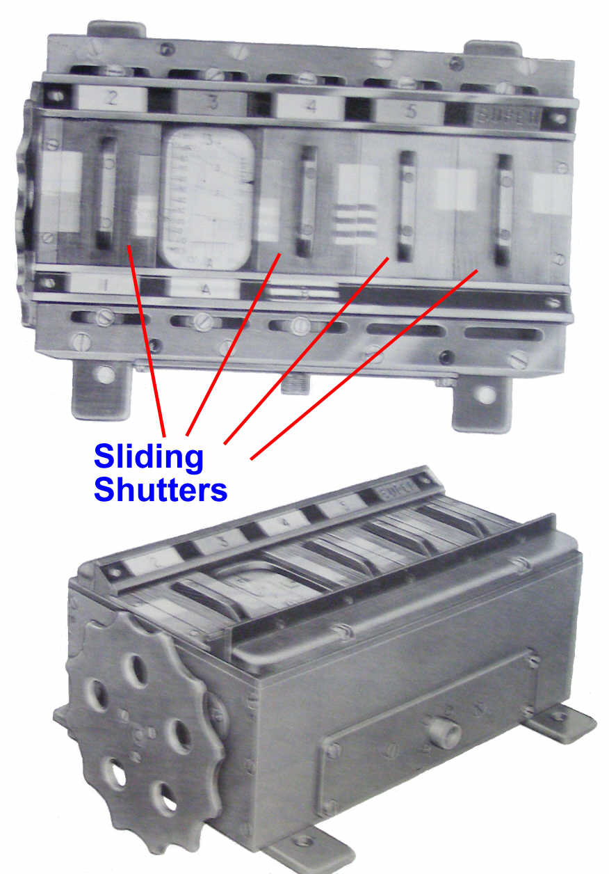
The 1947 decision offered two types of gun rule, the already used 'bar' pattern for each charge and a new 'shutter' type. The latter had a row of rotating drums in a box, one for each charge, with a transparent top. Each drum was marked with a set of curves for every 25 yards (or metres) of range and fitted with a cursor adjustable to the MV. Sliding shutters covered the top of the box to expose one selected charge. The SPs (105-mm Abbot, 155-mm M109 and 175-mm M107) had these connected to the gun's electrical power supply to give internal lighting. However, 105-mm L5 Pack How had a different solution - a handheld circular gun rule for each charge.
Figure 12
- Abbot Gun Rule
Click the picture
to see it enlarged
The 105-mm Light Guns (L118 and L119) were the first British guns designed since before WW1 not to have calibrating sights or a gun rule. These guns entered service in the mid-1970's, a few years after FACE. FACE computed an individual QE for each gun, not the range and Angle of Sight, so there was no need for a gun rule to convert range to TE.
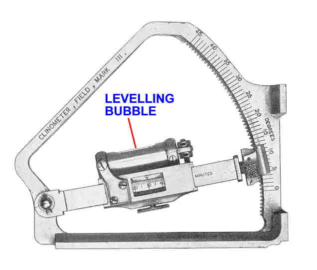
As a back-up a separate instrument, a field clinometer, was issued to each gun from 1910 onwards and eventually required with some procedures such as ‘precision ranging’, later called ‘destruction’. They were also required for sight testing. This clinometer, called a 'Gunners Quadrant’ in the US, had the QE set on it, and was placed on a surface parallel to the axis of barrel, such as the top of the breech. Figure 13 was the standard model in 1914, being copied from a foreign design. Many sight carriers included an elevation scale, graduated only in degrees (no minutes), to facilitate clinometer laying. A very different design was introduced with 105-mm Pack How, its configuration was compact much smaller than the traditional pattern and was essentially the same as a sight clinometer, but with the mounting at the base replaced by a plane. A similar configuration, albeit fully enclosed to enable Trilux lighting, was developed for Light Gun.
Figure 13 - Clinometer, Field, Mark 3
Click the picture
to see it enlarged
Sighting
Laying in elevation had a globally consistent reference, the horizontal plane that can always be found with a leveling bubble. Laying in azimuth at a target invisible from the gun was more complicated because there is no simple and easily accessible physical constant as a reference (until electro-mechanical gyroscopes).
The geometry for indirect fire laying was first worked out in the 1880's by the Russians. In 1882 Lt Col KG Guk wrote 'Indirect Fire for Field Artillery'. However, it needed a suitable sighting instrument. The Germans invented the Richtfläche, literally ‘lining-plane’ in English, in the 1890's. Its use spread over the following years.
Nevertheless the late 19th Century developments had older origins. The initial approach was to place aiming posts close to the guns and in line with the target. There is evidence that this technique was used by the Burgundians in the 16th Century and the Russians seem to have routinely used something similar in the mid 18th Century. UK used aiming posts with mortars from at least the mid 1800's. They'd been adopted with guns by at least the mid 1890's, a single post for each gun if the gunners could see the target and a pair of posts if they could not. The idea was to get the guns just out of the enemy's sight by deploying behind a crest - a 'covered position'.
The most useful way of aiming a gun at a target that was invisible to it required three azimuths:
However, initially the British did not adopt this, they reached it empirically through practical experience in the field having started with a simpler approach. The first azimuth sights evolved quickly and soon settled on an optical instrument called a 'dial sight' by the British and 'panoramic telescope' by the US. Nevertheless the British were relatively slow adopters, in 1901 they issued staff requirements for new guns (which became 13-pdr and 18-pdr) but did not seek indirect fire sights for them. They adopted such sights a few years later and called them 'goniometric sights' but soon changed to 'dial sight'.
Broadly, azimuth sighting evolved through three stages. The first stage was a simple deflection from an aiming point (AP) close to the line to the target. This used the facilities of direct fire sights, see Figures 3 - 7 above, although these only provided a deflection angle of a few degrees. During the Boer War some howitzer batteries used locally made gun-arcs to enable larger deflection angles for indirect fire. These arcs became an issued item, they were about one yard long with holes for a movable acorn foresight.
Figure 14 - Simple Deflection Laying
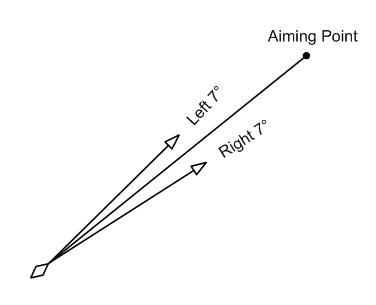
Next came use of a large angle between target and AP. The methods for this evolved quite rapidly over a few years
Figure 15 - Aiming Point Angle
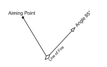
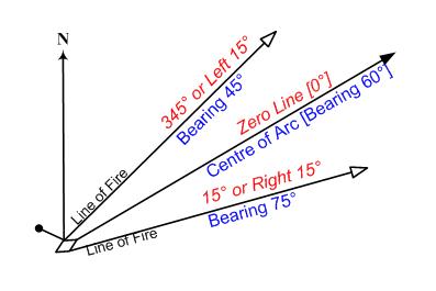
Finally, the guns were oriented in a known azimuth, used any suitable AP and recorded their angle to it, and were given the azimuth to a target that was known relative to their oriented azimuth. This method started with a zero line but in 1956 UK changed to a centre of arc bearing relative to grid north.
Figure 16 - Azimuth
The following sections trace this evolution in more detail.
The next section deals with orienting the guns so that they can be aimed at a target and the use and types of APs. The following section deals with dial sights.
In the late the 19th Century, when a pair of aiming posts was used to align the guns with a target they couldn't see, the procedure was simple. The Battery Commander laid out the position by placing a front aiming post in the line between the 'directing' gun's intended position and the target. A measuring line (knotted cord) was layed from this at a rough right angle to the direction to the target and each layer placed his aiming post at the correct distance from the directing gun's. The layers then placed their second aiming posts in line with the first and the target. The guns then deployed out of sight of the target but in line with their aiming posts. Each gun in a section (of 2 guns) had a differently coloured tops to its aiming posts to avoid confusion.
However, the carrier often had an integral open sight for direct fire purposes and a bracket for a sighting telescope, subsequently an anti-tank telescope, was fitted in some instances. Different guns had different sighting telescopes.
Early sights were not reciprocating. This meant that if the gun was on cross-sloping ground, one wheel was higher than the other (trunnion tilt), then the dial sight would be tilted to the side, not vertical. This meant that the dial sight 0° was not parallel with the axis of the bore. The solution to this was for the gun No 1 to note the difference in wheel height and use a rule of thumb to produce an angular correction that he applied to any angle from the director (or to an aiming point if that method had been used to orient the guns). This problem was solved by introduction of reciprocating sights, the dial sight carrier could be ‘cross leveled’ to make them vertical.
The concept of an indirect azimuth sight is simple. A gun has a sight that measures the angle between the axis of the gun's bore and another point. The bore is oriented in a known azimuth and using the sight the gunners record an angle to an aiming point. Firing data is provided as an angle relative to the known azimuth, this angle is added to or subtracted from the recorded angle to the aiming point and set on the sight, which is then aimed at the aiming point by moving the barrel. Initially the aiming point was close to the known azimuth, indeed the aiming post method described in the previous paragraph provided one and initial methods used sights offering only a few degrees of deflection from this azimuth. However lining plane type sights allowed far greater deflections such that an aiming point could be at any angle relative to the known azimuth.
Figure 17 shows the concept with the known azimuth being called a 'zero line' and angle between this azimuth and the target being called a 'switch' and an aiming point at a large angle from the zero line. This was the WW2 terminology.
Having indirect azimuth sights on each gun solved only part of the problem. The first step in using the sights was orienting the guns in a known reference azimuth. The quickly recognised ideal was that the guns in a battery were oriented parallel to each other. The eventual approach was to orient the guns of a battery so that they pointed in an azimuth towards their expected target area. Broadly, this evolved through several stages:
Laying on a target meant using an angle relative to the ZL. Initially, this angle was all that mattered and the actual orientation of the ZL didn’t matter. However, map shooting meant that the ZL azimuth became critical. It had to be a known angle relative to grid North (ie a 'grid bearing') so that when a bearing from battery to target was calculated from co-ordinates, the deflection angle from the Zero Line was accurate to the target.
The director was broadly similar to a dial sight. The first director, Director No 1, like the first model Dial Sights Nos 2 – 6 had an 'open sight' mounted on a horizontal scale. The horizontal scale could be aligned then angles measured against this alignment.
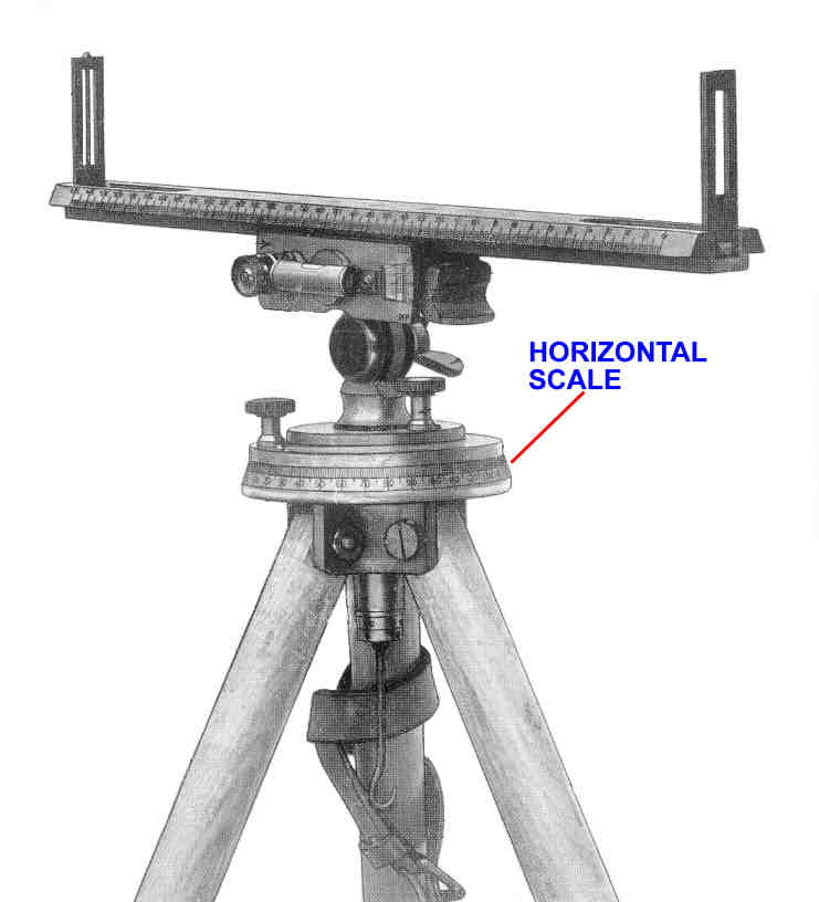
Figure 18 - Director, No 1, Mark 2 on Stand, Telescope, Field Artillery, Mark 1
In this first director the horizontal
scale was part of the director stand.
Click the picture
to see it enlarged
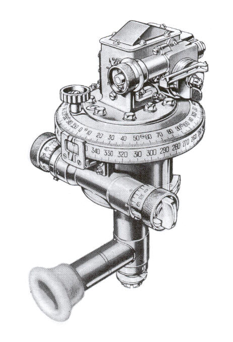
No 3 introduced in 1910, was an optical device. It was mounted on a tripod, great pains were taken to find the best design of tripod ‘holster’ for horse saddlery. The director had a ‘head’, a telescope in optical directors, that rotated through 360° against a scale graduated 180° left and right. However, with a director this scale could also be separately rotated on the director stand and locked in any position, hence 0° could be in any direction, unlike a gun where dial sight zero was fixed parallel to the barrel. No 3 had a field of view of 4° 20' and ×6 magnification. The No 2 director was introduced at much the same time and was generally similar. However, its 2° 10' field of view and ×15 magnification made it more suitable for target acquisition and being placed a greater distance from the battery position.
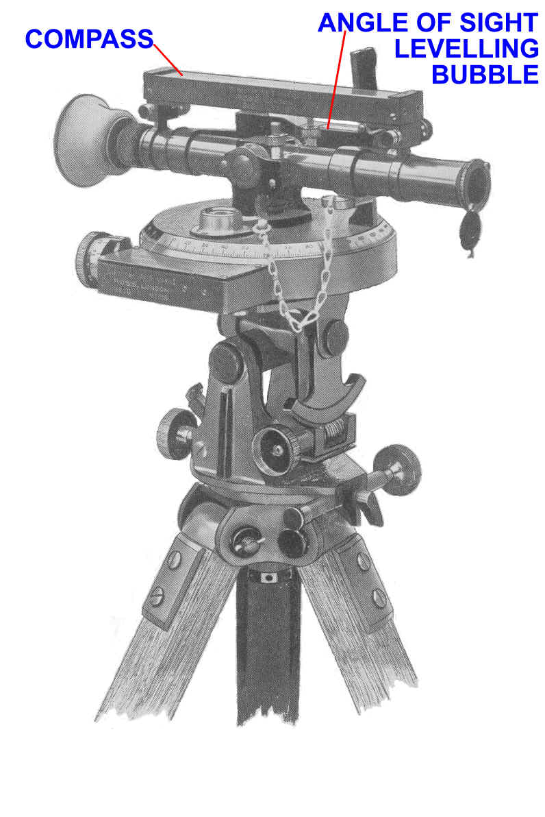
Figure 19 - Director, No 3, Mark 1 on Mark 1 Stand
Click the picture
to see it enlarged
The No 4 director, which had two different heads with telescopes providing different magnification appeared early in WW1. The lower magnification was for gun position use, while observers used the higher magnification head. There was a common stand for both heads, and this stand had the director's azimuth scale permanently fitted.
Figure 20 - Director, No 4
Click the picture
to see it enlarged
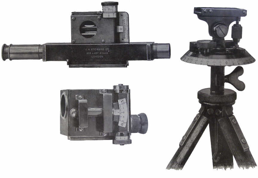
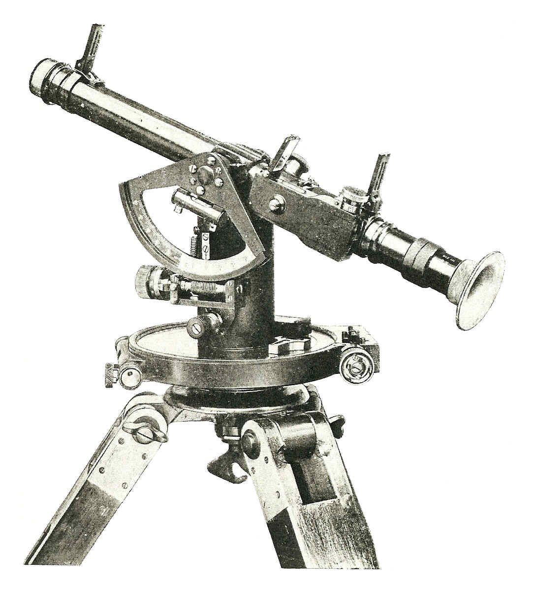
The No 5 Director was also introduced in 1915. This was a No 2 director modified by adding an elevation arc and scale to measure vertical angles up to ±50º. It also had an integral magnetic compass making it simpler to orient the director relative to North.
Figure 21 - Director, No 5
Click the picture to see it enlarged
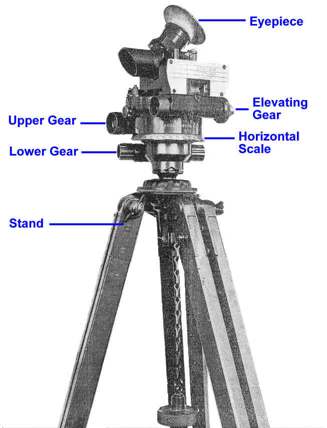
The No 7 Director (12° 30' field of view and ×4.5 magnification) appeared in the 1930's and was graduated from 0 to 360° for use with the later models of No 7 Dial Sight. It supplemented and gradually replaced the No 6 that had entered service after WW1 and was very similar in appearance and functions, No 7 was the longest serving director until the L1A1. The No 7 was a compact instrument measuring both vertical and horizontal angles. In the 1960's No 7's scales were converted to mils and its single point leveling arrangement was replaced by three leveling screws for use with Stand Instrument No 39, as used with its replacement L1A1 Director, see below. This stand had been introduced in WW2 with the Theodolite No 1.
Figure 22 - No 7 Director
Click the picture
to see it enlarged
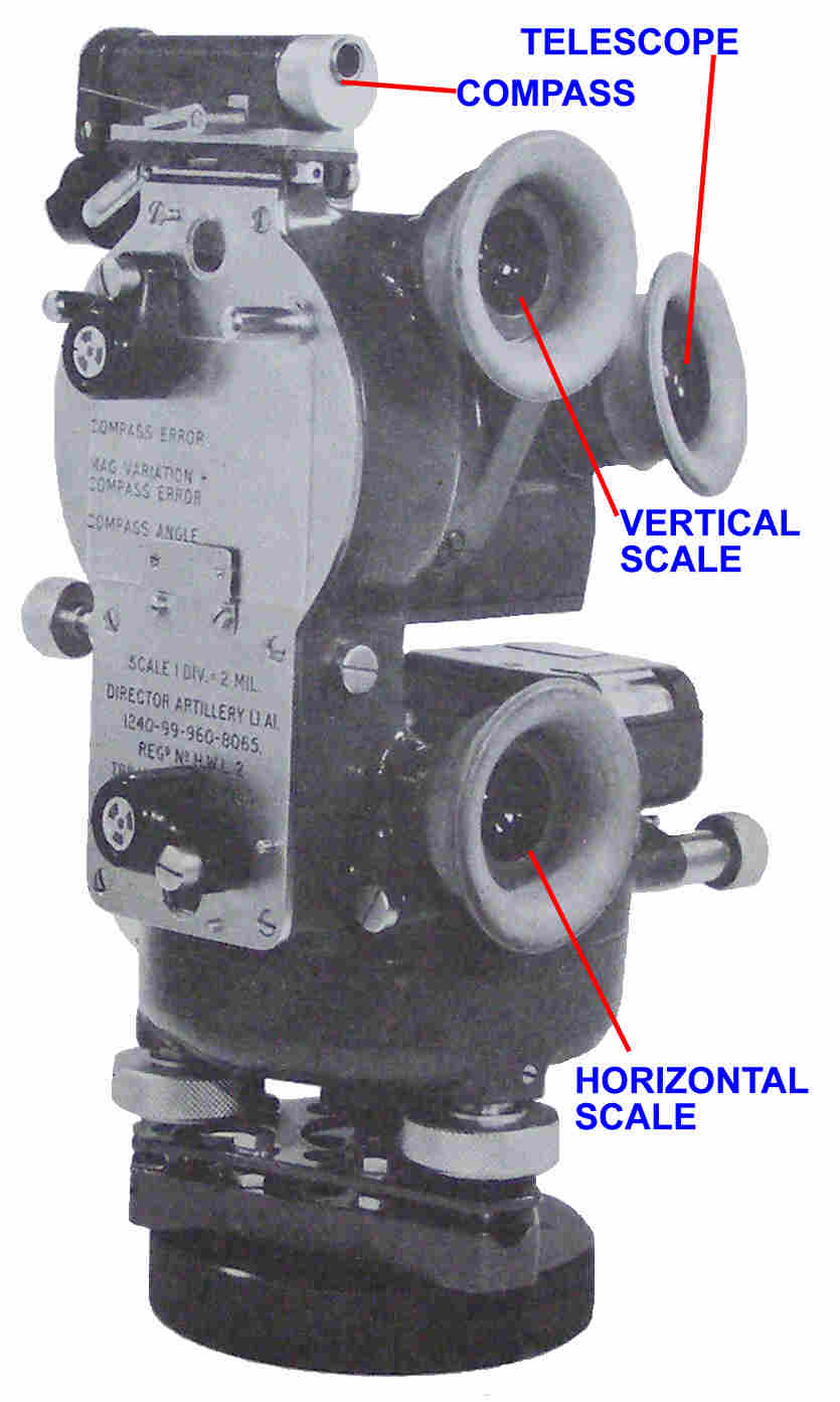
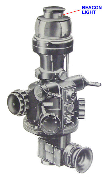
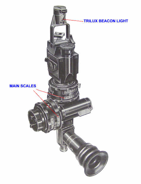
The final model of director, the L1A1 (200 mils field of view and ×4.5 magnification) replaced the No 7 in the mid 1960's and remains in use, albeit limited because all UK guns had become self-orienting by late 2002. It had internal scales and Trilux lighting. Directors can be confusing because coast artillery used their own and the numbering overlapped.
Figure 23 - L1A1 Director
Stand
not shown
Click the picture
to see it enlarged
A director could be used in two ways: Initially it was sited where the target could be seen.
Figure 24 - Director Measures AP Angle
Figure 25 - Individual Angles
Original method where director could see the target, in reality the range was much greater so the obvious offset in the figure did not exist. Subsequently the director was oriented in Zero Line or Centre of Arc Bearing
The director itself was the AP and the guns’ barrels made parallel to the director’s ‘line’ to the target. The detailed procedures evolved but the general pattern was:
Both methods were introduced before WW1. The limitations of the director being close to the guns and able to see the target soon emerged. This led to a second director able to see the target and the director near the guns. This too soon proved problematic. The solution was a zero line, and ultimately a centre of arc bearing, in the general direction of the target area.
The second, B, called the ‘individual angle method’, was soon modified so that the guns did not use the director as their actual aiming point. It eventually became the only method but it took over 50 years to reach this stage. Resistance to it was based on the experience that it took longer than other methods to orient the guns, speed into action was a vital element in British artillery thinking. The problems with the alternatives were that they could be inaccurate and increasing artillery range during the 20th century exacerbated this, furthermore they weren’t suitable for use at night, which also increased in importance during the century.
To avoid confusion it’s important to note that APs had two possible purposes and could be used for one or both of them. The unavoidable use was as an AP for individual guns, each gun could have more than one such AP (in case it lost sight to one) and could select its own. These APs were selected and recorded after the gun had been oriented. They included the gun’s aiming posts and auxiliary APs.
The second use of an AP was to initially orient the guns of a battery, originally as shown in Figure 24 above. In this use guns were given an azimuth to the AP that was the angle between the AP and the reference azimuth to target, ZL or centre of arc. Figure 24 shows this being measured with a director, but rougher methods could also be used. This AP was a distant and clearly defined feature. Selecting a gun position entailed finding a position with a suitable AP. Initially this was a prominent feature selected close to the line to the target. Of course finding a gun position with an AP that could be seen and was close to the line to a target that couldn’t be seen was not always easy! So the next step was to use an orienting AP that was not necessarily close to the line to the target. Ideally this was a extension of the gun line.
Figure 26 - Ideal Aiming Point Orientation Method
If the guns and aiming point were not in a straight line then each gun needed a displacement angle applied to the aiming point angle
Using the same AP angle for all guns introduced a problem unless all the guns and the AP were in a straight line (as in Figure 25), the guns would not be parallel. Taking a case where the AP was in the vicinity of the target, if the AP was about 5,000 yards away and the battery frontage about 100 yards, then the left hand gun was pointed about 1 degree to the right of the right hand gun. One degree sub-tended about 18 yards on the ground for each 1000 yards of range. Proper parallelism required an AP at infinity, with a minimum about 30,000 yards being a reasonable approximation for all guns in a battery, although no minimum distance was actually prescribed (probably because there was no way of measuring it).
Of course an AP at over 30,000 yards was highly improbable if not impossible, the magnification provided by the dial sight optics was nowhere near good enough even if a suitable visible feature existed. The solution was a displacement angle for the distance of each gun from the right hand gun. Depending on whether the AP was in front of or behind the guns, the displacement correction was an angle to either ‘converge’ or ‘diverge’ on the right hand gun. This angle reflected the apex angle at the AP for the length of the gun line. It was roughly deduced by sub-tension. Methods were using sub-tension angles per 100 yards in Range Tables, trigonometry, slide rule or 6/10ths rule if apex angle was less than 10 degrees. Individual gun corrections were a proportion of the battery frontage angle. They were ordered to each gun and the No 1 applied it to the angle to the AP.
The individual angle method avoided the issue of displacement correction because each gun received its own angle to the director as the orienting AP and this angle accurately included displacement. To orient the guns in a zero line the director was first oriented in North, then:
A related method was ‘parallel lines to No (gun)’. In this one gun was oriented by some means this gun then acted as a director for the other guns, with 180° added to the angle at the ‘control’ gun. It was very quick if the guns were in a straight line.
Using the director as the sole AP was a problem once firing started. When the gun was traversed or when the spades embedded during firing then the gun’s dial sight moved. These small movements altered the angle to the AP and if the AP was too close, as a director invariably was, then the fall of shot on the ground would be in the wrong place.
The procedure was soon changed. Each gun placed its aiming posts in a convenient position, usually to the front, as its AP. For this the gun barrel remained in the oriented position relative to the director but the sight head was rotated to align with the aiming posts. This angle was recorded. Another alternative also emerged and replaced using the director as the aiming point. It was the ‘auxiliary AP’, renamed ‘Gun Aiming Point’ (GAP) in the 1930's. With this each gun selected one or more distant GAP of their own and recorded them in the same way. A distant GAP was a topographical feature, ideally distant meant a practical approximation of infinity. Practical meant that any movement of the gun or its sight while firing would not alter the angle to the GAP.
The problem was that guns, or more specifically their sights, move. For example on soft ground guns move backwards when firing as the spades at the end of the trails 'bed-in'. Sights also move when guns traverse because the sights are off-set from the gun's traverse pivot, see Figure 17 above. These movements change the angle between the dial sight and its GAPs. For example, if a sight moves 12 inches and the GAP is only 50 yards away then in the worst case the angle to the GAP changes by about 2°, which represents about 350 yards on the ground if the guns are firing at a range of 10,000 yards. However, if the GAP is 2000 yards away a 12 inch move of the sight is an angular change of some 3', about 9 yards at 10,000 yard range.
Of course a distant GAP wasn’t usable at night, nor in poor visibility such as fog, mist, smoke or sandstorms. Furthermore at least two night GAPs were required in case one failed. A battery (or troop) ‘Night picket’ light was placed a relatively short distance behind the guns. The problem was that they were all too often far too close and did not approximate infinity, which caused inaccuracy in night firing if the gun moved or firing was at a large switch from the zero line. Being behind the guns minimised this problem, providing the gun position enabled them to be so placed (guns along the front of a wood were problem). Locally made lights were used, and in WW1 were probably 'Lamps, Siege'. During the 1930's 'Apparatus Illuminating Aiming Point' was introduced, complete with 3 foot metal picket. It had a separate dry cell battery pack and the light itself could also be fitted to an aiming post. During WW1 'Apparatus Illuminating Director' was issued. This had a separate battery pack, a vertical 'beacon' that emitted light in all directions (coloured sleeves were later added to differentiate the directors in a unit), and lamps for reading the scales and lighting the internal graticules.
There were two complementary solutions to this problem of close GAPs, procedural and technical. The procedural one was to periodically check the guns' orientation using a second director. The technical solution was to use close GAPs that gave artificial infinity when distant GAPs weren't available. These were aiming posts and the parallelescope for each gun.
Aiming posts were used in pairs by each gun, the posts being planted at about 50 and 100 yards from the gun, potentially in any direction but usually towards the front because this was out of the way of movement around the gun position. To reduce the scope for mistakes between the two guns in each section had posts with either different coloured or different shaped tops. Initially the posts were planted in line with the dial sight, as the sight moved a gap appeared between the two posts when viewed through the sight, the layer then looked for the pair of numbers on the cross bars that were closest and layed on the rear one. In Figure 27 the actual aim point would be '6'. In the 1950's aiming posts with cross bars were replaced with US style plain poles, with the layer aiming midway between the poles. However, aiming posts were seldom used by this time, the prism parallelescope being far better, with those for turreted SPs mounted on high tripods.
Figure 27 - Aiming Posts
World War 2 Pattern
Aiming posts could be lit, although with the British horizontal bar type, Figure 27, this was not simple. Then there was the issue of either leaving them on all night and using batteries or switching them on when required, either remotely or by a man going out to them.
However, there was another solution to an aiming point at an infinite distance. The parallelescope was introduced in 1917 as an alternative to aiming posts for simulating an AP at infinite distance and easily usable at night. At this time gun pits with overhead protection became usual in some areas and severely restricted the field of view out of the gun pit. Aiming posts are unsuitable when counter-battery fire can be frequent, which was the reason for overhead protection. The original Paralleloscope Mk 1 was a 3.7 × 2.9 inch mirror fitted to a horizontal slide about 22 inches long that was mounted on a stand to keep it horizontal and fixed in its position. Subsequent marks of parallelescope (the spelling changed) were a flat mirror about 2 feet long, the WW2 era Mk 5 is shown in Figure 28.
In 1955 a new type of parallelescope using a prism instead of a flat mirror was trialed. It was slightly wider with a more robust and stable mount, and mounted in a fibreglass container, the lid of which was used as a shade, making it invisible from the air. Using a prism instead of a simple mirror allowed greater height difference between the dial sight and parallelescope and eliminated the need to level the parallelescope precisely. It entered service in 1961.
Figure 28 - Parallelescope Mk 5 on Stand, Instrument No 27
A parallelescope was placed a few yards from each gun. With a parallelescope the layer aimed his sight on its reflection in the mirror. However, the early dial sights could not focus at less than 12 yards so a diaphragm with a pinhole or an additional lens was fitted to each sighthead. At night a torch could be held immediately above the dial sight head. Figure 29 shows how a parallelescope worked.
Figure 29 - Parallelescope Operation
The French introduced another method before WW1, the collimateur, it was trialed by 6 British batteries in 1914 but it was never adopted by UK.
Initially gun sights were ‘open’, merely a foresight and a backsight, and also used for direct fire although Sighting Telescopes were also introduced. There was a small amount of lateral movement in either the fore or backsight (or in the telescope mount) so that deflections could be set. In the Boer War some British batteries adopted locally made ‘gun arcs’ about a yard long, with holes for a movable foresight blade. This enabled greater deflection and became official after the Boer War. A similar approach using locally made gun arcs was probably used at Tobruk in 1941 where Italian guns captured without their sights were used.
However, the formal adoption of indirect fire by the British in 1906 meant that gun-arcs were replaced with lining-planes, by then called ‘goniometric’, sights. In mid-1907 the term ‘dial sight’ was adopted for British service. The original goniometric sights were flat circular metal plates with scales, graduated in degrees in British use, marked around the side, Figure 30. They had a centrally rotating strip mounting an open fore and backsight somewhat similar to the No 1 Director (Figure 18 ).
Figure 30 - Sight, Dial, No 1 Mark 2
Click the picture to see it enlarged
![]()
These sights were mounted on either the shield or a separate pedestal if the gun was shieldless. In essence they enabled the gun to a use an auxiliary AP at a large deflection from the target or primary AP, but the gun had to be oriented before this was done. This was simple but not very satisfactory.
The next step was to replace the open sight with a telescope and mount it in a manner that enabled it to be used to orient the gun. This meant the telescope had to be aligned with the bore, which meant putting the sight in the Sighting Telescope position on the side of the gun. These telescopes were an integral part of the sight assembly, which by this time included an elevation scale in some form and a gun specific arrangement for mounting it on the gun. In some cases the telescopes may have been the Sighting Telescopes issued for direct fire. This series of Dial Sights had different numbers up to No 6.
Figure 31 - Sight, Dial, No 4, Mark 2
The original lining
plane having been replaced by a telescope to give the Mk 2 sight
Click the picture
to see it enlarged
Initially these sights were used in a similar way to the arc sights they replaced. They were aimed at an aiming point (AP) that was no more than a few degrees azimuth from the actual target. It soon became clear that APs in any direction relative to the target were necessary. Figure 31 above shows that while the telescope could be pointed in any direction and had a full circle horizontal azimuth scale, it also had a separate deflection scale limited to 5 degrees left and right.
The problem with these early dial sights was that the layer had to move around to see through them to the AP if it was to a flank or the rear. This meant that in some positions he couldn’t reach his gun’s traversing handwheel. Different armies mounted these sights in different places on their guns. The Russians, for example, mounted their uglomer on top of the barrel just forward of the breach. Initially, British preference seems to have been atop the centre of the shield (eg 18-pdr) or on a pillar mounted on the side of the gun if there was no shield but the pillar soon became the standard. These sights, when mounted on the elevating mass of the gun, also adopted the 'independent line sight' design invented a few years earlier. This meant the azimuth sights could be set and layed before the gun was layed in elevation.
However, the contortions required by a layer to use such sights was clearly a drawback, and by about 1904 the Korrodi panorama sight was invented. This was a periscopic sight with an optical eyepiece in a fixed position relative to the gun (and its layer) and a rotating optical head that could be pointed in any direction. It meant that the layer could be in his normal position where he could use his traversing handwheel but his aiming point could be in any direction. The rotating head was sufficiently above the eyepiece that its line of sight was above the layer’s head.
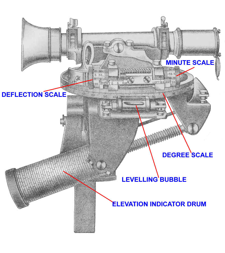
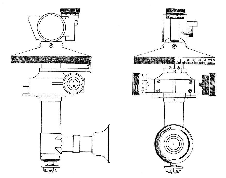
Several manufacturers produced Korrodi type panorama sights, and Zeiss unsuccessfully tried a different approach. After 3 years of trials UK adopted a modified version of the German Goerz panorama sight as Dial Sight No 7 in 1910, although it didn't actually enter service until early 1914. The main modification was ergonomic, the diameter of the horizontal scale was increased so that the markings could be larger, which facilitated supervision of the layer. Graduations in degrees and minutes (on a micrometer scale) would also have been a British modification because at this period the Germans used grads. UK manufacturing was arranged. Dial sight carriers specific to each type of gun, incorporating cross levelling arrangements, a sight clinometer and in most cases a range scale also had to be developed. However, the main cause of its delay into service was developing a suitable protective case for the dial sight and its carrier that could be mounted on the gun shield.
Figure 32 - Sight, Dial, No 7, Mark 1
Click the picture
to see it enlarged
The tricky bit in a dial sight design, apart from the overall precision, was keeping the image the right way up in the eyepiece as the cowl and its prism were rotated. Figure 33 shows the optical path. The rectifying prism is geared to the rotating head such that the prism rotates at half the rate of angular movement of the head, this keeps the image correctly vertical in the layer’s eyepiece. The No 7 Dial Sight had a 10° field of view and ×4 magnification. The No 7 Dial Sight also had a vertical scale geared to the prism in the cowl at the top of the sight. When the sight was properly cross leveled this enabled the angle to local crests to be measured for crest clearance purposes. This function was provided in all dial sights.
Figure 33 - Dial Sight Optical Path
In the 1930's a modified No 7 was introduced. This had an additional horizontal scale called the ‘slipping scale’ (later renamed the ‘shooting scale’) and associated micrometer scale. Whereas the existing scale, now called the ‘main scale’ was a fixed part of the sight, the new scale could be slipped and have its 0° graduation positioned anywhere relative to the main scale. This meant that when an AP was recorded on the main scale, the shooting scale was slipped to 0° (ie the Zero Line) or later the centre of arc bearing. The deflection (or bearing) ordered to a target was set on this scale. These two sets of scales became the norm.
Figure 34 - Various Marks of No 7 Dial Sight
Click the picture
to see it enlarged
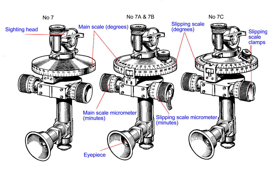
No 7 dial sights were graduated from 0° to 180° right and left, with a micrometer scale to sub-divide each degree into 12 divisions each 5 minutes of arc. The reason for this was probably the existing use of left and right deflections. Sights were changed to 0° to 359° in the 1930's but deflection laying was retained. When set to 0° on the main scale the sight head pointed forwards parallel to the barrel, which meant that any sight setting was the angle between the axis of the bore and the axis of the dial sight head. The sight head could also be elevated or depressed to cope with APs that were higher or lower.
During the 1930's 'Apparatus, Illuminating Sights, Mk 5' was introduced and each gun had one. It comprised a separate battery back and two lamps. Later dial sights had a window to which a light could be fixed to illuminate the internal graticules.
All later dial sights were functionally identical to the later versions of the No 7, although there were minor differences in features and mils replaced degrees and minutes. In about 1942 the No 10 Dial Sight was introduced as an alternative to the various marks of No 7. It seems to have been a lower cost 'austerity' instrument. It is not clear if it was much used with field artillery, however, it became the standard sight for 3.7-inch heavy AA guns when used against ground targets. Its distinctive feature was having the rectifying optics in the eyepiece stem instead of the vertical 'tube', the eyepiece had a curved section in it that held the prisms.
The No 9, which was very similar to the final mark of No 7, appeared late in WW2 and replaced the No 7 over the following years. A mils conversion was first produced in about 1960 for Honest John rocket launchers and 203-mm guns, a dial sight adaptor was used to fit the dial sight into the US sight carrier. Subsequently it was used with 25-pdr and 5.5-inch when they were converted to mils in the mid 1960's and lasted into the 1990's on 175-mm and 203-mm guns. With a service life of nearly 50 years No 9 was the longest serving dial sight.
Figure 35 - No 9 Dial Sight (Degrees)
Click the picture
to see it enlarged
105-mm Abbot being a fully enclosed and turreted SP gun required a new approach, a periscopic sight. This sight, No 3 Periscopic, had only internal scales, that were read under magnification, with the main or shooting scale being selected for viewing. Being vehicle mounted this sight had internal electrical lighting as well as an integral light beacon to provide the director with an aiming point at night.
Figure 36 - Abbot Dial Sight
Click the picture
to see it enlarged
105-mm Light Gun also had a completely new dial sight, a modified version of the German Leitz Rblf59 instrument designated L7 in UK service. It broke with the past by having an eye-piece that could swivel and not having the wide diameter scales that had characterised all previous British dial sights. Perhaps because experience with the Italian dial sight of the 105-mm Pack How demonstrated that they were unnecessary. The new sight also had both micrometers on the left side. The original sight had them on the right, presumably to accommodate the majority of right handed users. The problem was this was less than ideal for someone double-checking that the sight was correctly set so it was moved to the left. Other UK modifications were sliding shutters to selectively conceal the main and shooting scales and their micrometer scales and Trilux light sources including in a detachable beacon for use with the director at night. Trilux eliminated the need for battery powered lighting.
Figure 37 - 105-mm Light
Gun L7 Dial Sight
Click the picture
to see it enlarged
All British guns had their dial sights on the left hand side (looking from the rear - but some photos are reversed in printing!). In WW1 the dial sight was usually removed from heavy guns before they fired. The sights used for indirect fire with mortars and medium or general purpose machine guns were simplified dial sights lacking the panoramic feature (there’s not much to climb around with a mortar or MG).
Three foreign dial sights were introduced in the 1960's and '70's. An Italian one used with 105-mm Pack How, it was not well suited to tropical conditions because moisture could get inside the sight causing the optics to fog up. German sights were used with both 155-mm M109 and FH70.
Optical sights, directors and leveling bubbles were 20th Century technology. The first step in a new direction was the laying system in 155-mm SP70, an ill-fated tri-national venture. However, UK was responsible for much of the turret design and one feature of the sighting arrangements was no cross leveling. Instead trunnion tilt was measured and the angle to the AP automatically corrected for it. During the 1970's both UK and US developed Positioning and Azimuth Determining Systems (PADS) as survey devices for their artilleries. These used electro-mechanical gyroscopes similar to those in aircraft inertial navigation systems. However, it was clear that gyroscopes and electronic clinometers could be used to self-survey and lay guns and launchers. The Multi-Launch Rocket System (MLRS) was the first platform to use this.
UK introduced 155-mm AS90 in the early 1990's. This gun, like MLRS, was autonomous (it self-surveyed, did not need any external instrument to orient it or GAPs to provide a reference angle) and did not have a dial sight or leveling bubbles. It had ring laser gyros (RLG) for azimuth, elevation and trunnion tilt. Electronics detected when the gun was layed in the required bearing and elevation and in SP equipments with powered laying the process is automated. However, its reversionary mode laying is a step back into history, the direct fire telescope is used with deflections from an AP.
The use of directors and optical sights with their need for GAPs finally ended in 2002. In that year all British artillery completed the change to electronic 'sights' when all 105-mm Light Guns were fitted with the Artillery Pointing System (APS), mounted above the ordnance and aligned with the axis of the bore and the trunnions. The heart of APS is also three RLGs, each in a different axis to measure azimuth relative to grid north, elevation relative to the horizontal plane and trunnion tilt relative to the other axis of the horizontal plane (also called roll). This unit subsequently replaced the older Honeywell system in AS90. The next step is likely to involve each gun predictively correcting its elevation for the expected MV of the next shell it fires based on the MVs of previous shells, a new form of calibrating sight!
The effect of these systems is to significantly reduce 'into action' time for a battery, in any weather and particularly at night. 'Quick actions', where batteries deploy from the 'line of march' wherever they are, are especially faster and with the same accuracy as a traditional deployment on a surveyed position. Freed from the need to lay using external APs means the guns can fire in zero visibility that even prevents use of a parallescope, such as a sandstorm or when weather conditions prevent smoke dispersing from the gun position.
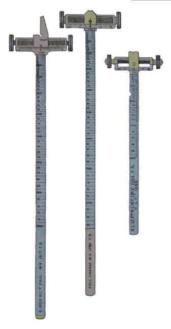
Until 1915 shrapnel was the primary weapon of British field artillery and it remained important through the inter-war years. Shrapnel had to be burst in the air, and getting the height of burst correct was critical for its successful use. Airbursting meant using some form of time fuze. Just as there was a relationship between range and elevation angle so too was there a relationship between fuze length and range that was further influenced by MV. However, getting the right fuze length for a shell descending at hundreds of feet per second required precision. Until a new generation of fuzes started appearing in the 1950's British fuze lengths were not based on standard units of time such as seconds. They used arbitrary values.
The fuze length for a range could be produced in one of two ways, either read from the Range Table or from a fuze indicator at each gun. The obvious way was for the observer to order corrections to the fuze length, the time that was set on the fuze. However, the British recognised that there could be several targets engaged in an area and that moving targets needed to be shot at - accounts of the Boer War include 'chasing' Boer horsemen across the veldt with shrapnel. They therefore adopted the corrector. This adjusted the standard tabulated fuze length for a particular range, in effect it allowed a fuze correction for non-standard conditions to be found by ranging and then applied to other targets at different ranges, angles of sight and or azimuths in the zone of fire. The benefits for rapidly engaging successive or moving targets are obvious.
The normal corrector setting was 100, the observer adjusted this by bracketing until he got the average height of burst where he wanted or the correct ratio of ground burst to airburst. Each gun had a fuze indicator, a large slide rule, marked with ranges, fuze lengths and corrector settings. In effect the corrector was an off-set to the standard relationship between range and fuze length. One of the gun detachment set the ordered corrector against the ordered range and read the fuze length to be set on the fuze.
During the 1930's fuze indicators were further refined by enabling the cursor to be adjusted for the gun's MV - the same idea as applied to range with Probert pattern sights. This gave a corrector setting for MV variation from standard before shooting started. A different fuze indicator was required for each charge, and in some cases for different types of fuze. The fuze length, determined with the fuze indicator, was set on the fuze using a spanner like 'fuze key'. During WW2 fuze setters appeared and were issued to each gun. The fuze length was set on this, which was then used to set each fuze, it reduced the likelihood of fuze setting errors.
The corrector method outlived shrapnel and was used with mechanical or powder burning time fuzes fitted to HE shells and remained in use until the adoption of ABCA procedures in the mid 1960's. With this the older method of ordering changes (lengthen or shorten) to the actual fuze became the only method, of course by this time using mechanical time fuzes with HE was dying out as VT fuzes became more available.
Like gun rules, fuze indicators lasted until FACE was introduced in 1970. FACE computed a fuze length for each gun. Electronic fuzes introduced in the 1980's used electronic fuze setters, which also tested that the fuze was correctly functioning.
Copyright © 2006 - 2014 Nigel F Evans. All Rights Reserved.