|
BRITISH ARTILLERY IN WORLD WAR 2 |
|
GUN CHARACTERISTICS |
This page describes the main parts and assemblies of a gun, as used by British designers.
|
Updated 6 June 2014 |
|
|
|
|
|
|
|
|
|
|
|
|
|
|
|
|
|
|
|
|
|
|
|
|
|
|
|
|
|
|
|
|
|
|
|
|
|
|
|
|
|
|
British practice was to describe a gun in terms of its two or three main assemblages - the Ordnance, the Carriage and or Mounting. While they had recognised that Guns and Howitzers were traditionally different, after World War 1 (WW1) they also recognised that the characteristics of the two were merging. Detailed technical data for British guns is given in data sheets through the 'Guns' page.
Traditionally a Gun had limited maximum elevation, British Guns seldom more than about 20°, to give a fairly flat trajectory, a single propelling charge, and a relatively high muzzle velocity with a relatively long barrel. In contrast, Howitzers had a maximum elevation approaching 45° to give a high trajectory and steep angle of descent ('plunging fire'), a choice of propelling charge sizes, and a relatively low muzzle velocity with a relatively short barrel. The new generation of guns that appeared after WW1 combined some features of both Guns and Howitzers by having a maximum elevation of 45° or more, a choice of charges, and a relatively high muzzle velocity. Some nations adopted the term 'gun-howitzer for these and this had some unofficial British use before WW2.
However, from 1939 the new generation of British artillery omitted either term from their official designations. Instead the designations comprised an Ordnance name and mark number and a Carriage or Mounting name and mark number. Before and during WW1 the term 'piece' had been commonly used as a collective term for both Guns and Howitzers, but by WW2 it had fallen from general use. However, they perpetuated confusion by continuing to use names that gave either shell weight or the calibre of the barrel. This nomenclature had been introduced in the late 19th Century, Guns were designated by the weight (in pounds) of their standard projectile while Howitzer names used calibre (in inches).
'Ordnance' was the term the British used for the components comprising the barrel group, designed to propel projectiles by explosive force. The Ordnance was supported by a Carriage or Mounting. This component group provided a stable support for the Ordnance and comprised the superstructure and the basic structure.
Figure 1 - Structure of a Towed Gun
A Carriage was a support that had its wheels (or tracks) in contact with ground when the Ordnance was fired. A Mounting rested directly on the ground when the Ordnance fired, Mobile Mountings had wheels that were raised from the ground when 'in-action'. In WW2 almost all British field artillery used carriages, while AA artillery used mountings or mobile mountings. SP guns were more complicated and eventually classed as 'SP carriages' with 'SP mountings' between the SP Carriage and the Ordnance.
On towed guns the superstructure had two main elements: the cradle and the saddle. The saddle had some degree of rotation about the pivot and at its top provided bearings that supported the cradle trunnions and enabled it to be elevated. The cradle had trunnions that rotated in the bearing on the saddle. The cradle contained or supported the recoil system and supported the barrel. The barrel either had integral slides or was fitted in a jacket or slipper with slides. These slides allowed the barrel to slide down and up the cradle during recoil and run-out. The ordnance and cradle together is sometimes called the 'elevating mass'.
The mounting on a SP gun is basically the superstructure comprising the cradle and supports that functioned as a saddle, including elevation gears and traversing gears in some configurations. It was fixed to the SP vehicle.
The main components of an ordnance are the barrel and breech. Ordnance design involves complex interaction with ammunition design. Field artillery put a premium on light weight, and the ordnance is usually the heaviest single part of a gun and drives the weight of the carriage. For a given strength of steel ordnance weight is a function of its size including barrel length and the size of the chamber. In particular a large chamber meant a larger ordnance, a smaller chamber often meant more energetic propellants that burnt hotter and increased the rate of barrel erosion. Higher chamber pressures also meant stronger barrels, which also increased weight. British WW2 guns typically had a working pressure of about 15-16 tons/sq inch, this peak being reached when the shell had traveled a few inches and then falling away in another few inches. There are many design factors and tradeoffs that have to be considered.
The barrel is the most obvious feature of the Ordnance, and the time WW2 was one of change because monobloc barrels were appearing for ever larger calibres. Monobloc barrels, as the name implies, are machined in their entirety from a single piece of forged steel. In essence this was being brought about by advances in metallurgy that enabled steel of sufficient strength for barrels of acceptable weight and machine tools that could precisely work these large pieces of metal at a speed that enabled mass-production. The problem was to produce a barrel that could contain the various firing stresses:
Before monobloc construction became feasible for larger calibres most nations, apart from the British, produced only 'built-up' barrels. These comprised tubes inserted one inside another, with the inner diameter of each tube being slightly less than the outer diameter of the tube that went in it The outer tubes were heated to expand them, when they cooled they compressed the inner one. In WW2 UK generally limited monobloc barrels to under 4 inches calibre and built-up barrels were limited to large coast and naval calibres. However, there were exceptions to most things and 7.2-inch Mk 1 and Mk 6 ordnance were monobloc.
Wire bound barrels were widely used by the British in the early part of the 20th century in addition to built-up barrels. The 18-pdr Mk 4 had a typical wire bound field gun barrel. The inner most tube (A Tube in British terminology) was bound with steel wire for about the rearmost third of its length. The wire-bound barrel was then fitted in a jacket.
Figure 2 - Ordnance 18-pdr Mk 4 Cross-section
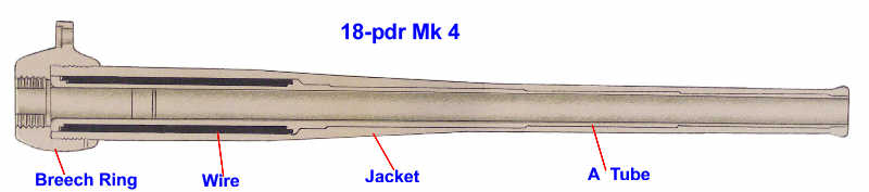
The 18-pdr Mk 4B ordnance dispensed with wire binding and used the construction that most British WW2 guns used, a 'loose liner' in a jacket. The loose liner was, of course, a tight fit. It was called 'loose' because it wasn't part of a built-up barrel and could be removed from the jacket and replaced when it was worn. The jacket provided the interface between the ordnance and the carriage or mounting as well as providing additional strength. The WW1 era guns generally had a jacket that went the full length of the barrel. However, with the WW2 era guns the jacket generally went only about halfway.
Figure 3 - Ordnance 25-pdr Mk 2 Cross-section
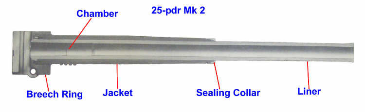
Loose liner construction was enabled by the introduction of autofrettage ('self-shrinking'), a strengthening technique that removed the need for wire binding. Autofrettage had been invented by the French in the early 20th Century and adopted by the British in 1920. British guns of WW2 mostly had autofrettaged loose liners.
Barrels for autofrettaging are machined to slightly less than their calibre and then subjected to high internal pressure, either hydraulically or using a swage. This expands the metal closest to the bore beyond its elastic limit, but the outer metal remains within its elastic limit and so compresses the inner. The bore is then heat treated to raise its elastic limit. The result is that for any particular grade of steel an autofrettaged barrel can be thinner and hence lighter for a given strength.
In British guns rifling is always right handed and in WW2 it was mostly constant because the benefits of increasing twist were outweighed by other factors. By WW2 the rifling was generally the 'polygroove plain section' design. This had a depth proportional to calibre, with groove and land widths proportional to depth and radius curves instead of corners at the bottom of the groove. Rifling causes twisting forces on loose liners when a shell is fired, so combing or feathering and featherguides have to be used to fix the liner in its jacket.
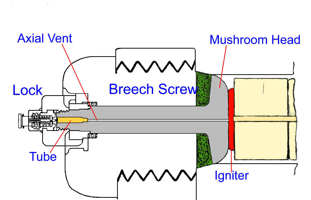
A breech comprises a breech ring screwed to the barrel and a breech block with mechanisms for closing the breech, providing obturation and a means of firing. The main determinant for these is whether the ordnance is Breech Loading (BL) or Quick Firing (QF). In BL designs the breech provides obturation and a 'tube' (very small cartridge sometimes called a 'primer') loaded into the lock attached to the outside the breech provides propellant ignition. In QF obturation is provided by the metal cartridge case and propellant ignition is from a primer fitted into the cartridge case and struck by a firing pin in the breech block. QF breeches also have 'extractors' to free the cartridge case from the breech after firing. Figure 4 shows a closed BL breech (ie the block screwed into the ring) with a bag cartridge in the breech chamber. 'Lock' is a longstanding term, as in 'flintlock' and 'matchlock'.
BL breeches always used a breech screw as their closing mechanism. Screw breeches, supported by a carrier, were closed by being swung in on a hinge and twisted to lock them in. Interrupted threads were used to minimise the amount of screwing, and the British used the Welin non-tapering three stepped thread type that was typically closed by a 30 degree rotation in BL breeches. This enabled a short breech screw that could be inserted and closed in a single 90 degree upward motion of the breech mechanism lever, or opened in one motion by downward movement of the lever. The Asbury mechanism, used on most British BL guns from late 1916, converted the vertical movement of the breech lever into the rotating movement of the breech block.
Figure 5 - Welin Screw - Late Mark 5.5-inch
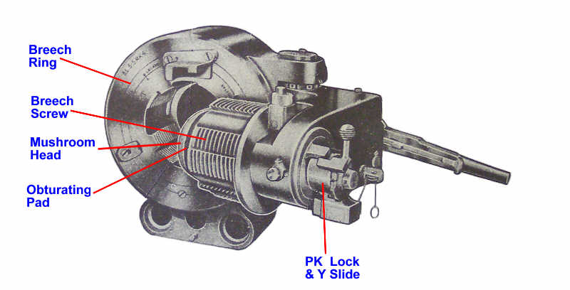
BL obturation with a screw breech uses a steel 'mushroom-head', with a slightly flexible backing, fitted to the inner face of the breech block, this is pressed back by the pressure of the propellant gases to seal the breech. However, the breech block and mushroom-head are penetrated by an axial vent as part of the firing mechanism.
QF had mostly used screw mechanisms in WW1, the 4.5-in Howitzer being a notable exception, but by WW2 new designs used sliding blocks. The block could slide either vertically or horizontally, and the breech ring be either 'closed' or 'open'. The latter meaning that it was three sided, with the gap in the side where the breech block came out. QF breeches also had 'extractors' to eject the empty cartridge case when the breech was opened.
Breeches alone were insufficient, they had to be some form of firing mechanism and this was fitted to breach. It housed a percussion firing pin that was spring powered, a trigger to release it and mechanical safety linkages to prevent the trigger operating until the breech was properly closed. The firing pin struck the primer in the base of a QF cartridge or the separately loaded tube for a BL ordnance. By WW2 the trigger action for QF guns was 'fired' by a manually operated firing lever mounted on the cradle with mechanical linkages to the firing mechanism inside the breech block, the firing mechanism was cocked and fired in a single action. For BL guns a lanyard, attached to the lock, was used.
The firing mechanism for BL guns comprised a lock and slide mechanism that fitted over the tube chamber in the breech screw, the tube was loaded manually into the tube chamber when the breech screw had been closed. The lock prevented a tube being loaded until the breech screw was closed and had extractors that removed it when the lock was opened. At the beginning of WW2 a PL Lock and AC Slide Box were standard but these were replaced during the war by a new design the PK Lock and Y Slide Box. The main difference was that the PL Lock had a large 'lock hand lever' fitted to the breech ring that opened, closed and cocked the lock. The PK Lock had a small integral 'lock actuating lever' for opening and closing, and cocking was part of the firing sequence when the lanyard was pulled. The lanyard was short and pulled from the side, not long and pulled from the rear. See the 'Ammunition' page for more details about BL ammunition.
Two other components appeared as part of some British ordnance in WW2. The most obvious were muzzle brakes, which were a feature of anti-tank guns but were also introduced for the 25-pdr in 1943 to enable it to fire anti-tank shot using charge Super plus increment. A muzzle brake reduces recoil forces by re-directing some propellant gas in a direction to counter-act some recoil.
The other component appeared on some WW1 era ordnance, an oil tank to keep the recoil and run-out mechanism 'topped-up'. 18-pdr and 7.2-inch are examples. In 25-pdr this tank was a replaced by a replenisher, a cylinder that was part of the recoil assembly in the cradle.
There are two parts to a carriage:
The cradle supports the ordnance and in most British designs contained the mechanisms to control recoil (buffer) and run-out (recuperator). Where the ordnance had a jacket this had guides that fitted into guide-ways on the cradle, which enabled the ordnance to slide backwards during recoil and forwards on run-out. For guns without a jacket, such as 3.7-inch How, the barrel was fitted to a slipper that provided the guides. These guides and guide-ways provided part of the interface between the ordnance and the carriage or mounting, the other part being the piston rods connecting the ordnance to the buffer and recuperator.
Some guns shared the same carriage design, typically a 'gun' (longer range, smaller shell) and a 'howitzer' (large shell, shorter range). In WW1 the 6-inch Gun and 8-inch Howitzer were good examples. In WW2 the 4.5-inch and 5.5-inch followed this pattern although both were usually called 'Guns' despite having calibre in the name. The US 155-mm Gun and 8-inch Howitzer, and 8-inch Gun and 240-mm Howitzer are a pair of examples used by UK, although the UK used 7.2-inch instead of 8-inch Howitzer.
It was the invention of recoil systems in the late 19th century that enabled 'quickfiring' guns. In essence these mechanisms enabled a gun to absorb its own recoil and so not need manually repositioning after every round fired. Of course the original recoil systems were fairly simple. They were used with guns that fired at low elevation angles - no need to worry about high angles and the recoiling mass hitting the ground - and being used with 'real' guns they did not have to worry about coping with different charges and hence different recoil forces. However, the general requirements for recoil and run-out arrangements are fairly simple. They need to cope with multi-charge ammunition firing at all elevation angles, and they must provide smooth recoil and run-out - no violent hitting against 'stops'. They also need to be very reliable and maintainable by gun detachments in the field.
Guns use a buffer (often called a high pressure cylinder) to control recoil and a recuperator (often called a hydraulic cylinder) to control run-out. In essence the recoiling ordnance pulls a piston in the buffer cylinder back with it. This piston moved against oil that could move from one side of the piston to the other, which had the effect of absorbing the recoil. In early guns the recoil also compressed one or more springs that provided the recuperator. However, effective hydro-pneumatic recuperators had been produced by the French before WW1, they used glycerine to move a floating piston that compressed pressurised air instead of springs. The British improved on this by using oil instead of glycerine, and the design used with the 6-inch Howitzer provided the model for many later British guns. The difficult bit was sealing, with 'packings', the sides of the piston to prevent compressed air leaking into the oil. Figure 6 shows the entire arrangement schematically. There is no flow of oil between buffer and recuperator, and the pressurised (uncompressed) air pressure was typically between 600 & 800 lbs/sq inch.
Figure 6 - Buffer Recuperator Action
Of course the actual details were more complicated, with features to fully control recoil and run-out so that the pistons didn't hit the ends of the cylinders. The British generally used a rotating piston that progressively decreased the flow of oil, and a small control piston at the end of the buffer. The buffer's oil also had to be kept topped-up, either by a gravity fed tank on the ordnance or by a tank in the cradle, or in the case of the 25-pdr, a replenisher cylinder parallel to the buffer and recuperator cylinders. Each gun had a separate hand-pumped compressor as part of its stores in order to 'top-up' the air pressure when necessary.
Most guns, including British ones, also had another feature, cut-off gear. This adjusted the actual length of recoil depending on the elevation angle of the ordnance. Greater elevation meant that more recoil forces were being directed into the ground, it also reduced the space for recoil (unless recoil pits were dug). Cut-off gear automatically reduced the length of recoil as elevation increased.
Large calibre guns needed a loading tray to present the shell at the breech from where it was rammed. Sometimes the cradle extension that projected rearwards beyond the breech when the gun was run-out was used to support this, particularly for split trail guns. More usually with box trails the loading tray was positioned onto the trail. Some heavy guns had a wheeled 'loading bogey' that was pushed along the trail with the shell on it. Very large guns usually had hoisting arrangements to lift the shell up to where it was rammed. These guns usually had either a specific loading angle or upper and lower elevation limits for loading. These limits were due to the need for two or more men to ram the shell, which could only be done at a fairly low elevation angle. It obviously reduced the rate of fire, although 4.5 and 5.5-inch had a 'quick release' gear that enabled the barrel to be 'dropped' to the loading position.
The combination of ordnance, cradle, buffer and recuperator is sometimes called the 'elevating mass'. When its centre of gravity is not at or very close to the trunnions then balancing gear is needed to provide support and remove load from the elevating gears. In most cases there was also a traveling clamp to lock the cradle to the carriage when the gun was being towed and with some guns the ordnance was drawn back for towing by disconnecting the jacket from the buffer-recuperator in the cradle.
Sights enable a gun to be layed in line (azimuth) and range (or elevation). Almost all British guns used 'one-man laying' (18-pdr was the exception). This meant one man layed the gun for both line and elevation, the implications were that the handwheels had to be on the same side of the saddle and, more importantly, that the sights enabled a fast and efficient laying process. One man laying was achieved by having a dial sight carrier that provided laying in elevation. In contrast the US guns introduced during WW2 were all two-man laying.
In WW2 British guns used sights that were independent, calibrating and reciprocating. Independent sights had been introduced before WW1, it meant that the dial sight was not tilted when the barrel was elevated. Reciprocating meant that the dial sight could be cross-leveled to keep it vertical, a canted sight (due to the ground sloping across the gun - one wheel higher than the other) meant that the sight was not properly layed in the ordered line.
Calibrating meant that range, in yards, was set on its range scale, but this range was offset by the sight to compensate for the difference of the gun's muzzle velocity (MV) from the standard MV. This eliminated the need to calculate a MV correction for each gun for each of its targets, which meant targets were engaged quicker. In WW2 almost all British guns had calibrating sights of the Probert pattern, which had been introduced in the 1930's.
Since range was set on the sight, separate arrangements had to be made for angle of sight. This vertical angle was set on a Sight Clinometer, and this instrument provided the leveling bubble for laying in elevation. On some guns the correction for drift could be set directly on the dial sight carrier.
British sights therefore comprised a 'Carrier, Dial Sight' that was fitted to the trunnion protruding from the left side of the cradle. It provided mounts for the dial sight and sight clinometer, and the range scale with adjustable readers that were set to the MV for each charge. Guns also had a separate 'Field Clinometer' for use if required. This was set with the elevation angle, placed on a plane surface aligned with the axis of the bore (usually the breech block), and its bubble leveled by elevating the barrel.
The WW1 heavy and siege guns were mostly converted to calibrating sights in the 1930's. Some guns with non-calibrating sights were provided with a gun rule. Before the introduction of calibrating sights guns used a range scale marked in degrees and minutes that did not compensate for MV variation from standard.
More details about sights are laying are in the 'Sights and Laying' and 'Laying and Orienting' pages.
The cradle was mounted in the saddle using trunnions - horizontal pivots that were part of the cradle and rested in bearings in the saddle, this enable the elevating mass to rotate in the vertical plane. The saddle (sometimes called the 'carriage body') could also rotate horizontally about a vertical pivot that was part of the basic structure, this enables traverse, often called 'top traverse' to differentiate it from traverse by moving the carriage. Associated with both elevation and traverse were gear arcs, gear wheels and their handwheels, and some guns had coarse and fine gearing or quick release mechanisms to drop the barrel to its loading angle.
In simple terms a gun is stable when, as shown in Figure 7, Weight × Length is greater than Recoil × Height. This makes the trails the key component of the basic structure to ensure stability. Clearly this introduces interesting design challenges when weight is critical, which was the British view of field guns. The original specification for what became the 25-pdr limited the weight to 30-cwt, that of the 18-pdr Mk 5. In the event a changed General Staff Requirement requiring more range resulted in a weight of some 35-cwt and great stability.
Figure 7 - Gun Stability
Low trunnion height is also important and spades at the ends of the trail also help. During the 1930's trunnion height was reduced with the change from wide diameter wheels used with horse teams to smaller diameter pneumatic tyred wheels used with vehicle traction. Recoil forces can be reduced by a muzzle brake and longer recoil length helps the energy dissipate. In guns that do not have high velocity anti-tank ammunition the need for stability can be reduced by not firing the highest charge below a certain elevation angle. An additional stability issue is that a gun may approach instability when firing at close to its top traverse limits of the carriage. The problem particularly afflicts guns firing at top charge and low elevation on split trail carriages, exacerbated by sloping ground.
A feature of some post WW1 guns was that the trunnions were not close to the ordnance centre of gravity, but well behind it. There were several advantages in this, most notably that it permitted higher elevation angles with larger calibre (and longer barrel) guns, without the trunnions being unacceptably high. However, it also meant that the elevating mass was out of balance and required additional support (forward of the trunnions) or restraint (behind them). The British term for this was 'balancing gear' although the US calls the devices 'equilibrators'. British field guns using them in WW2 most obviously included 4.5 and 5.5-inch (having the same carriage) useing vertical compression springs, and 3.7-inch HAA.
Trails are a critical part of carriage design. Carriage trails can take one of three forms:
The first box trail and platform combination was the 18-pdr Mk 4 in 1918, but the 25-pdr is the best known. However, while the British used box trails with heavier guns in WW1, such as 60-pdr Gun, and 6-inch and 8-inch Howitzers, that lasted into WW2, their replacements, 4.5-inch and 5.5-inch Guns both used split trails. These had reasonably wide (60°) top traverse, which meant they didn't need traversing on their wheels too often, and were not expected to engage tanks (although it seems this occasionally happened).
Most trails had spades at their ends that dug themselves into the ground with the first few rounds fired. Although in some cases spades had to be hammered in before firing. The 25-pdr did not need to use its spade when fired from its platform, because this transferred recoil energy to the ground, so its spade was covered by a removable 'banana'. On the other hand with the 7.2-inch Mks 1 - 4 very little recoil energy was absorbed by the ground so large 'chocks', called scotches, were put behind the wheels which ran back up them with recoil then dropped forward to be stopped by small scotches.
Before WW1 almost all guns were horse-drawn and used wooden wheels with steel tyres, weight being the main consideration. During WW1 'traction engine' type large steel wheels appeared on heavy guns with carriages. However, the advent of vehicle towing at speeds faster than a traction engine meant new wheels were required and in the inter-war period the British upgraded their carriages. First they introduced wooden or steel wheels with solid rubber tyres that could be towed by horse or vehicle (the carriage Marks of such guns had the suffix 'R'), but they were unsuitable for 'high speed' towing. Then pneumatic (suffix 'P') tyred wheels were introduced for vehicle towing. During WW1 siege guns with carriages (eg 6-inch Gun and 8-inch How) were usually placed on constructed platforms, either timber or Vickers pattern, that were dug into the ground. This seems to have stopped with the conversion to pneumatic tyres, presumably because these were easier to traverse on their wheels.
The problem with these new pneumatic tyred wheels was that they had a far smaller diameter that the older ones, which had several consequences. This meant that the original axles couldn't be used, which necessitated lower axles to maintain trunnion height but reduced ground clearance when being towed. They were also harder to man-handle because smaller wheels offered less leverage.
New guns such as 25-pdr were designed with pneumatic tyres and lower height, and so had no 'P' suffix. Wooden wheels were retained as an option with 3.7-inch How when it was used in a pack role because they were more compact.
Of course new brakes were also required with new wheels. Vehicle towing for heavier guns demanded gun brakes synchronised with the tractor and the British used electric brakes on their modern guns. This presented a problem when the US 155-mm Gun M1 was introduced and its carriage adopted for 7.2-inch Mks 5 and 6. US practice was to use air-brakes with heavy guns and in consequence British heavy artillery tractors could not safely tow guns on the US carriages.
Changes to wheels also meant that artillery trailers (often incorrectly called 'limbers') had to change. Artillery trailers performed the functions of a limber, ie supporting the trail for towing, an essential requirement with horse draught. While they weren't essential for vehicle towing they were fitted to carry ammunition, gun tools and stores that would otherwise have to be carried in the tractor. The were specific to each gun, not least because of the ammunition size. A new range of pneumatic tyred trailers were introduced in the late 1930's.
The final feature of carriages for smaller guns was the gun shield, designed to protect the detachment from small-arms fire, they also provide some protection against shell splinters. In WW2 they were most important for anti-tank guns. A shield was designed for the 5.5-inch but was not adopted. A shield had another useful function, like the trail it had various fittings to carry gun tools and stores. During WW2 an additional refinement was to use double shields, separated by a spacer, to give extra protection. This was used with 25-pdr (and anti-tank guns).
A mounting is a carriage that rests on the ground, this simplifies the absorbtion of recoil force. Mountings were used for heavy howitzers in WW1, notably 9.2-inch that lasted into WW2. These were moved in several loads with assembly and disassembly when arriving at and leaving their gun position. The ordnance had to be mounted (and dismounted) to the carriage, a timber platform constructed and ballast box filled with several tons of dirt. By WW2 mountings were usually on three or four trail like stabilisers with the wheels raised, British examples are the 2-pdr anti-tank gun and the 3.7-inch mobile HAA gun. The US M1 pattern carriage for 155-mm Guns and 8-inch Howitzer, and with the British 7.2-inch How Mk 6, took a different approach. They had a split trail basic structure. This rested on the ground (with spades at both ends of both trails in pre-dug holes) with screw jacks incorporated into the wheel bogies used to raise and lower the wheels (and hence lower and raise the mounting). Nevertheless the US super heavy 8-inch Gun and 240-mm Howitzer were broadly similar to the old 9.2-inch How but with split trails and without the ballast box and constructed platform.
The most notable post war activity were various attempts to introduce fully armoured self propelled carriages for 25-pdr and 5.5-inch, this lasted until the late 1950's and failed due to policy changes. However, there was some thought to a 110-mm gun with 17,000 yard range, and in the early 1950's a towed 88-mm field gun, the Garrington Gun, was designed to replace the 25-pdr. It had a box trail with the legs above the detachment and providing the structure for its most obvious feature: its shield, which provided top and some side as well as frontal protection, a response to the introduction of VT fuzes and nuclear weapons. This gun taught the need for a fume extractor and did not enter service due to NATO's adoption of 105-mm as the standard calibre for light field guns.
Next was the 105-mm L109 with the L13 ordnance, better known as the Abbot tracked SP (FV433), introduced in the mid 1960's to replace 25-pdr, 5.5-inch and 155-mm How M44 in regiments stationed in Germany, it lasted until the early 1990's. Abbot had a forward engine and rear mounted fully enclosed turret with 360° traverse that was becoming the standard SP configuration first adopted by the US 105-mm M52 in the early 1950's. In accordance with British armoured vehicle design practices it used electrical servos, not hydraulics, to drive traverse, elevation and loading mechanisms. It also used an entirely new design of 105-mm ammunition (there was no multi-national ballistics MoU for 105-mm). This used an electrical firing mechanism instead of a percussion firing pin.
Two towed guns followed, first the Gun 105-mm L118 (Light Gun) introduced in the mid 1970's. This was designed as a replacement for the Italian Oto-Melara 105/14 Model 56, designated 105-mm Pack Howitzer L5 with L10 ordnance in UK service, that had been introduced in 1961 as a replacement for 25-pdr, 75-mm and 4.2-inch mortars in regiments outside Germany. L118 was designed to be light-weight and fire the Abbot Mk 2 ammunition family. It is a box trail and platform design using high strength light-weight steels (and some titanium in improved versions) and enterred service in the mid 1970's. It also has two ordnances, the L118 used the L19 ordnance for Abbot ammunition and the L119 with the L20 ordnance for M1 ammunition, both used the same L17 carriage. UK only used a handful of L119 for training, but the US Army adopted it with a few small modifications as the M119.
The second towed gun was the tri-national Howitzer 155-mm L121 with the L22 ordnance and commonly called FH70 (UK reverted to 'howitzer' in deference to the other nations). This gun was the first 'new generation' 155-mm and set the pattern for many other guns produced by various countries. The British designed the basic structure and coordinated the overall design. It entered service in the late 1970's as a replacement for the remaining 5.5-inch and left British service in the early 1990's. In British terms FH70 was a mobile mounting since its wheels were raised from the ground and the gun rested on a sole-plate, it was a split trail design. This gun was one of the first to use an auxiliary engine that gave it limited self-propulsion and powered hydraulics that assisted in bringing it in and out of action, with hand-pumps for backup. The gun had other novel features such as a BL ordnance with sliding-block breech, a primer magazine, burst fire (3 rounds in 15 seconds) and an electronic repeater display for its sights.
The final gun was another SP, 155-mm L131 (AS90) with the L31 ordnance introduced in 1992 to replace Abbot and M109. It was designed for the FH70 ammunition family. Its main innovations were fully autonomous laying and semi-automatic turret magazine and loading, it too uses servos and has an auxiliary engine to provide electrical power without relying on battery charging by the main engine.
During WW2 the Germans, who mostly used QF sliding block mechanisms, sought ways to use BL cartridges with sliding blocks because of the material resources needed for metal cartridge cases. This work was taken over by the British and reached fruition with the 1960's 120-mm L11 tank gun in Chieftain. The next was a Rheinmetall design in FH70, this used a metal obturation ring. The British found this wore out unacceptably fast, so for the 155-mm ordnance used in AS90 adopted their own design involving a split sliding block with a mushroom-head. The particular problem for modern BL guns with 'burst fire' capabilities is the need for a magazine to hold and automatically load the tubes, which is more complicated with a screw breech.
Finally, at the end of the 20th century, there was a change in terminology. BL became BO (breech obturation) and QF became AO (ammunition obturation).
Copyright © 2003 - 2014 Nigel F Evans. All Rights Reserved.