The two speed supercharger is something I thought up one night. While I'm sure it has been done before, I've never actually
SEEN a multi-speed supercharger.
The basic idea is that the BLUE belt in the
picture above is continuously running (as per any other typical supercharger).
When the engine is at LOW rpm and extra power is desired, an Air Conditioner
type electro-magnetic clutch is engaged and the RED
belt is used.
Due to the smaller pulley on the supercharger input shaft, the speed will
be much higher than usual. If the pulleys were appropriately sized, it
would be possible to have full boost at an engine speed near idle!
As a further refinement, it would be possible to slip the clutch so the
supercharger's input speed was maximum across the rev range. Naturally
this would only be used when it is really required, as the wear on the
AC clutch would be quite high - however I think the friction material is
reasonably easy to renew.
Note: Both the "slow speed" and "fast speed"
pulleys on the supercharger input shaft would use a bicycle style freewheeling
hub, otherwise if they were on a single fixed shaft they would fight against
each other when the "fast speed" was enabled.
I'm sure this could be much more nicely done with some sun/planet gears,
but I think what I've suggested could be done with easy to get components.
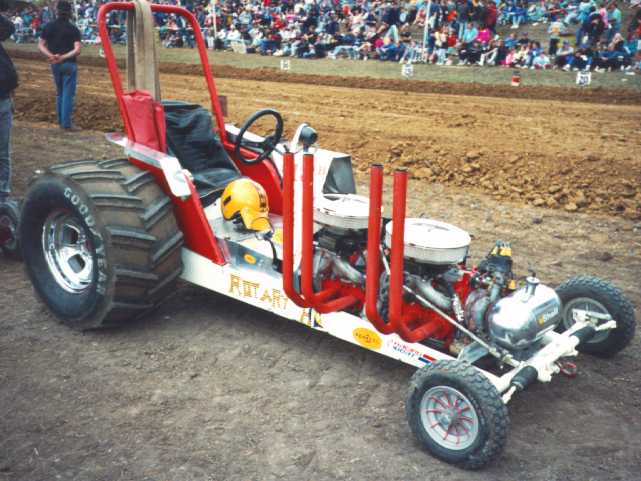
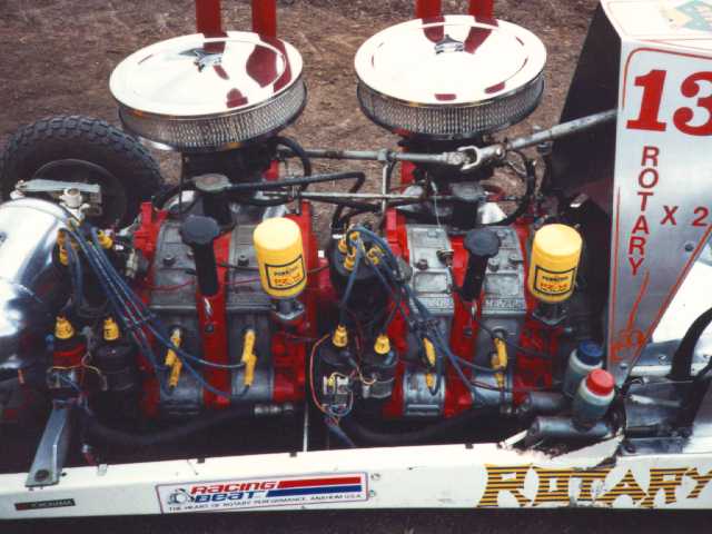
Home Made 4 rotor engine
Amazing but true.. It is possible to make your own 4 rotor
engine!
The basic idea is to couple the two engines together with some motorcycle
gear wheels and some double row chain.
I saw this arrangement on a 4 rotor tractor pull machine in about 1990.
The two engines need to be mounted accurately on a sub frame, to minimise
angular distortion of the chain drive. (the chain drive has some flexibility,
but not much).
The guy I spoke to said that there was a little bit of machining to be
done, but all the raw components were "off the shelf".
If I were considering building this for a street car I think using a CV
joint from a big car (eg FWD V6) would be better than the chain drive.
The application this was used in had two street port 13B engines with a
Holley carburettor each and tuned length open exhaust. That would make about 200hp
for the front engine, which would probably be about the safe limit of the
chains.
It used a 3 speed Automatic with 5000rpm (stall speed) torque converter and Ford 9 inch differential
"Granny's speed shop" has a fairly extensive article about joining two
13B engines.
This idea was originally created by Mazda during the mid-late
1960s with experimental engines. It was also used in Cosmo racing engines.
However, as the Cosmo engine made a mere 2 horsepower more than the standard
production engine the idea was not used thereafter. (This small gain is
probably because of the noise restrictions placed on it, hence not being able to
use a suitable exhaust system).
My friend resurrected the idea and
to recently it has been used by others. Due to the
sizeable intake ports - the peripheral ports are 45mm diameter plus
the street ports, the volumetric efficiency is very impressive. Volumetric
efficiency is a measure of the ratio of the combustion chamber size to how much
air can enter the engine while the intake port is open, and in turn the more
air/fuel mixture the higher the power.
In fact,
this engine MAY almost be over 100%. This means that the engine takes in more
air than it's capacity, which is unusual for a naturally
aspirated engine - normally only turbocharged engines and highly tuned racing
engines are capable of this. This explains why a peripheral port engines are
high powered.
In fact, a 13B with this configuration with a Holley carburettor,
electronic ignition, muffled exhaust has been dyno tested at 350
BHP ("flywheel horsepower" -calculated by the dyno)
Furthermore, due to the peripheral port secondary being a "static column of air", this tends to stop the traditional peripheral
port rough idle. This is because the air is not flowing into the port,
so it has a certain amount of resistance to movement or 'springiness' which limits how
much of the exhaust gets around the apex seal into the fresh mixture.
Also, as the air tends to be very turbulent due to the air streams colliding,
atomisation is good, resulting in a torque curve which is quite flat across the RPM range.
Given the characteristics across the RPM range, this engine
combination is almost comparable to a turbo engine. It was not much more
difficult to drive than a standard engine. The only problem is that this
engine requires a reasonably free flowing (noisy) exhaust.
Construction of the engine
The "Mazda Factory" primary ports in the intermediate
housing are filled with epoxy such as Devcon or similar, as described in the
Racing Beat catalogue.
The street ports are a conventional street port. Sorry, I'm not sure of
the exact port shape or timing used, but I think it was fairly close to
stock to enable good low down torque (which is also boosted slightly by
the relatively long induction tubes.)
The peripheral ports are made by having a machine shop bore a hole into
the housing. Into this is pressed a sleeve which has an interference fit
along with some industrial epoxy.
(The sleeve made out of a certain type of aluminium close to that of the
housing (i.e. same thermal expansion rate), "interference fit"
means that the hole is 45.00mm, while the sleeve is 45.05mm.. this ensures
a very tight fit that won't move!)
The sleeve then needs to be cut off and ground back 1-2mm from the inside
of the rotor housing. This avoids the apex seal being damaged or worn prematurely.
A bonus of this method is the ability to make it "look stock"..
Essentially this means that the port is flush with the surface where the
side housing ports are.. That is to say that the ports are in the SAME
PLACE as where the water flows from the engine to the manifold. Because
of this, the manifold can bolt directly onto the engine and seal the port-manifold
gap with a stock manifold gasket!
(Usually the connection between the manifold and the port intake is done
with a short length of radiator hose and some clamps.. yuk!!)
Limits of the engine
What are the limits of the peripheral port design? Maybe
it is possible to use some big bridge ports where the original (Mazda factory)
ports were. If the improvements in engine breathing can make 350hp with
a street port and a peripheral port, maybe bridge ports would make 450hp??
We also thought that a peripheral port further around the housing could
be used successfully with a turbo.. Just like racing beat's peripheral
port turbo 900 hp 3 rotor 13G engine!!
An even weirder idea would be to put in TWO peripheral ports per
housing! an intake 45mm wide x 90mm long is a mighty big port!! Another option is to run the engine on methanol. Due to methanol's
characteristics of taking heat out of the air as it evaporates, this cools
the air making it denser. Denser air = higher volumetric efficiency = higher
power. (a bridge port on methanol makes 250+ hp).. Perhaps it would be
possible to make 500hp from a naturally aspirated engine!!
The "Scoot" RX7 uses the normal side intake ports plus a peripheral
port and a single turbo to make over 700hp from a 13B.
(Semi) Distributorless
ignition
Not a new idea - Mazda have used this
technique since the 2nd generation RX7 (1986-1991).
The basic idea is that on a two rotor engine, the leading plugs may be
fired simultaneously, with one spark igniting the fresh air-fuel mixture
in one of the rotors, while the other rotor will have a "waste"
spark that will fire into the already burnt/still burning exhaust gas.
This is due to the geometry of the rotors being 60 degrees
out of phase (when measured from the apex seals) - See example
above.
One major provision is that the timing is not advanced
nor retarded too much, as this may cause the 'waste' spark to undesirably fire
into some fresh mixture. For this reason, this technique
will not work on the trailing plugs.
Essentially a "dual ended" ignition coil
is used, simply connected to the existing leading ignition system. For example, a General Motors 3.8 V6 coil used with it's distributorless
ignition. The whole system can be put
together in under an hour if you have all the correct connectors and
ignition leads available.
The advantages of this system are mainly that much higher voltages including CDI
(Capacitor Discharge Ignition) can
be used as there is no distributor cap to route the high voltage through, without
fear of cross firing to the trailing spark plugs.
'Surface
discharge' type spark plugs may be used - which replace the conventional ground
electrode with a ring of metal around the centre conductor. I believe this
allows more spark discharge paths, giving better ignition of the air-fuel
mixtures.
In terms of power gain over a conventional
early Mazda ignition system that uses a distributor, about 5% extra power
may be gained.
Turbo Lag Minimiser
I can't claim the inspiration for this one, however I
think the way it is done is unique!
In the late 90s Toyota used a system on their rally cars of pumping extra air and fuel into
the exhaust before the turbo. This then keeps the turbo spinning over at
high RPM to avoid turbo lag out of corners. This has the disadvantage of
being noisy and heating the turbo(s) up significantly, plus interfering with the
engine's normal fuelling system.
My method uses high pressure and volume air to spin up
the compressor side of the turbo. (Try aiming a water hose at a bicycle
pedal and you will see the effect).
In fact you are not supposed to allow bearings to free turn in a compressed
air stream as they can gain such high speed they can fail explosively.
A good quality 12 volt compressor is hooked up to an air
tank, with a solenoid valve feeding through a hose to the turbocharger,
where a hole is drilled through the side of it (at an angle)-see below
for estimated sizes of the hole. My initial thoughts are that perhaps a
standard workshop air compressor tank could be used, as it is likely to
be reasonably safe, in any case I would run the pressure much lower than
the recommended operating pressure of the tank (maybe 100PSI?). I'd imagine
that the air line would have to be reasonably large, like about 1/2 inch
internal diameter, to allow a high flow rate to empty the tank in a few
seconds.
The solenoid valve could be triggered to operate when the engine is given
full throttle (like an automatic transmission kick down switch). A further
refinement would be clutch and gearbox switches so it is only operated
when actually in gear and moving.
Estimated specifications:
These are based on high school mathematics and first year of an engineering
degree. I don't know much about thermodynamics
per se! They are probably not accurate, due to all the pressures
and temperatures changing rapidly but should give a rough picture of what's
happening!
An 8cm diameter compressor wheel turning at 100,000 RPM, in 1 second requires
(for air speed to match the speed of the wheel at it's outer edge):
*A 1/2 inch diameter nozzle will require 51 litres of air
*A 3/8 inch diameter nozzle will require 30 litres of air
*A 1/4 inch diameter nozzle will require 13 litres of air
A 13B engine running at 1000 RPM, assuming 80% volumetric efficiency (about
what a wide open throttle no boost 13B gets) requires 34.7 litres of air
My "Gut Feeling" tells me that the 1/4 inch nozzle would probably
be enough, simply because the volume of air is about 1/3 or what the engine
needs at that speed, plus the extra pumped in by the higher compressor
speed. As the 13 litres of air at turbo pressure is probably only 3 litres at compressed air pressure, a 20
litre compressor tank should be more than
enough for 4 or 5 seconds use (as the pressure in the tank will drop during
that period).
Things to consider in this situation are as per most air compressor situations..
Condensation may form in the tank or as the air leaves the tank, an appropriately
designed and certified tank should be used, particularly considering the
extremely fast pressure drop. High quality hoses and fittings should be
used (a hydraulic repair service should be able to help with this, as hydraulics
operate at well over 1000 PSI). The solenoid valve should be rated for
the pressures involved, as well as shutting off when a high airflow is
under way. Another concern is the rapid drop in temperature of the air
as it drops in pressure may produce severe thermal stress when it is introduced
to the turbo, perhaps cracking the compressor blades.
Perhaps fitting the nozzle to the turbine (exhaust) side of the turbo would
be better, but the risk of thermal stress would be higher. Another serious
alternative to this would be to use a nitrous system when the engine is under
low boost, but nitrous has it's own problems.
Drag racing air operated
clutch and traction control system
Recently some manufacturers have started making manual gearboxes with
automatic clutch actuation, and BMW's M3 even has a 'fast launch' mode that I
understand works in a similar way to this - but no doubt is elegantly
integrated!
This system is essentially intended to put some intelligence into the operation
of the clutch (in a manual transmission car).
The basic idea is that the clutch is slipped while the engine is at it's
maximum RPM (or perhaps where it makes it's peak torque or power). This is very similar to the way top fuel drag cars
work, with a staged clutch running on timers.
This system goes one better in that it will only allow the clutch to grip
enough for maximum acceleration, and will back off if the wheels break
traction.
The heart of the system is the air operated clutch slave
cylinder, which is controlled by some solenoid valves. Compressed air allows
fast operation of the clutch.
The brains of the unit would be set up to calculate if
the drive wheels were spinning by comparing the drive shaft speed with
the speed of a front wheel (which would normally be in contact with the
ground). If the rear wheels are turning faster than the front they are
obviously spinning. In order to reduce the spinning the clutch will be
"slipped" more, reducing the power going to the wheels and hence
stop the spinning and regain maximum traction/acceleration.
In order to change gears, a switch built into the gearstick
would be required to detect when you are pulling on it to change gear.
My initial impression is that this could be achieved by a heavy duty
videogame type joystick, such that the tension on the end would activate
the switch and operate the clutch, for a super fast gear change.
In some situations it may be necessary to reduce the engine
power along with disengaging the clutch, such as a high output turbo. This
would be necessary to avoid totally cooking and/or breaking the clutch
and/or the gearbox. Engine power can be reduced by retarding the ignition
slightly/missing sparks (done on cheaper cars with traction control) or
by another throttle body (as on Lexus V8 engines).
Finally, this set-up should be used with a rev limiter.
I think that it would be possible to drive with the foot flat on the accelerator
and just pull on the gearstick.
Given most manual car's 1/4 mile performance, this system would have to
be worth at least 1 second over the 1/4, all else being equal!
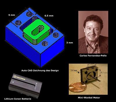
"Toroidal" rotary Engine
Similar idea to a Wankel rotary engine, in that there is a changing volume
of the combustion chamber to get the intake, compression, ignition, expansion,
exhaust for a conventional combustion engine to work.
(This picture was emailled to me).
Industry is trying to find smaller, longer lasting battery technologies for
devices such as laptops and other portable electronic equipment. One possible
solution is micro-machined combustion engines that run a generator. The Wankel
is possibly suitable for the same reasons it makes a good car engine - compact,
powerful, low vibration.
Other solutions include using a micro-machined jet turbine engine. Personally I
think it is more likely that some kind of fuel cell is more likely to be
successful, but a great idea nonetheless.
(This picture was emailled to me).
Adding a second oil cooler to
3rd generation (92-97) RX7s
This text was originally sent to the RX7 mailing list
on Thu, 14 Aug 97 by Jim White (jwhite@htc.honeywell.com)
(I only copied the message and tidied it up a bit for this page)
The US versions of the RX7 - base, touring or PEP (popular
equipment package) have ONE oil cooler
Only the "R1" and "R2" models have TWO oil coolers
- despite all 3rd generation RX7s having the same engine.
(Australian, European and Japanese RX7s - I don't know what models have
what)
I did it with parts from Mazda Competition Parts. Here's
my parts list and notes:
Item
Part Number
Description
Qty
$US (ea.)
Note
1
N3A1-14-710B
Hose, oil
1
52.60
Eng. to #4
2
9938-11-400
Bolt, connector
1
2.35
#1 to eng.
3
9956-21-800
Gasket
2
1.30
For #2
4
N3A3-14-830A
Hose, oil
1
223.40
Btw. coolers
5
9978-60-616
Screw, tapping
1
1.60
#4 to frame
6
N3A2-14-780B
Bracket, oil cooler
1
22.40
Outer bottom
7
9993-70-600
Nut
3
1.75
For #8,#6,#13
8
N3A3-14-700
Cooler, oil
1
366.05
Right side
9
FB01-56-81X
Fastener
3
1.05
#10 to #8
10
N3A2-14-708
Duct, oil cooler
1
25.70
conn. to #8
11
9078-60-630
Screw & washer
1
1.10
#8 to #6
12
9978-60-812
Screw, tapping
?
1.05
#13 to frame
13
N3A2-14-770B
Bracket, oil cooler
?
8.15
Inner top
14
N3A1-14-622
Stopper, connector
3
5.05
Conn. clip
I tried to be careful, but WATCH OUT FOR TYPOS! Almost
all of this is on page 1-i-6 of my '94 parts fiche (section 1500).
Prices shown are from Mazda Competition Parts and are
for quantity one. Multiply by the quantity column to get total prices.
Don't forget freight (UPS) and tax. Maybe $75 or so.
The notes are kind of terse, but if you look at the diagram
on the fiche I think they'll make sense.
One of the #7 nuts is not obvious, the other two are shown
on the diagram. It connects one of the brackets to the frame panel that
runs vertically just in front of the coolant overflow bottle at the right
front corner of the car. I had to remove the right wheel well liner and
the coolant overflow tank to get the nut on.
The connector clips in #14 aren't really necessary if
you don't mind reinstalling the old ones, but the shop manual says replace
and I wanted to be safe, so I ordered new ones for the three connections
that had to be opened. The connectors that come with the oil cooler (#8)
and hose (#1) include new clips. I also wrapped some tape around the connector
to help ensure that the clips don't come off.
I removed my air box, intercooler and battery just to make
it easy to get to the hose connections and to remove the old hose from
the engine to the left oil cooler. It might be easy to get to the hose
connections from below, but the bolt that holds the hose at the engine
block (#2) is right above the frame and behind a bracket holding the other
hose (the one that doesn't have to come off). You might be able to re-use
the old bolt, but not the gaskets (#3), and I figured for $2.35 it was
a good idea to replace it. By the way, it's 23mm.
I didn't disconnect any coolant lines or the coolant tank
that mounts on the intercooler. I just left it connected and moved it out
of the way. I dropped the front sway bar and removed it's mounting brackets
so that I could install the oil lines (#4) without removing the lower radiator
hose.
I did drain the oil from the block before starting and
used a pan to collect the remainder that came out of the hoses and existing
cooler as I disconnected things. Check the oil cooler section of your shop
manual (pages D-8 and D-9 in mine) before you start. It shows how to get
to the nuts (two of #7) on the top side of the oil cooler by removing the
headlight bezel.
I originally ordered items 12 and 13, the found out that
I didn't need them because the bracket (item 13) was already on my car.
All it was doing was providing a hole for a wiring harness mounting clip,
but it was there. If you take off the right headlamp bezel or the right
side air duct plate (on the bottom), you should be able to see if it's
there.
30 LED Air-Fuel ratio meter
Here's a circuit diagram for a 30 LED air-fuel ratio meter
using a standard automotive oxygen (akas "lambda") sensor.
I built one about two years ago and found it worked reasonably well-certainly
much better than a 10 led meter.
The design is by Khouri Giordano and he posted it to the RX7 mailing list
back in 1994.
These meters work by displaying the voltage on an exhaust
"oxygen" sensor - all modern EFI cars use these to tune the engine
continually.
The sensor is essentially a small battery that varies it's voltage depending
on the oxygen content in the exhaust, which reflects the air-fuel ratio
the engine is currently tuned at.
Unfortunately the common (cheap to make) ones have a very sharp response, i.e. only a fraction of a volt
separates a wide range of air fuel ratios
- furthermore the voltage output changes quite dramatically depending on
the temperature.
Standard EFI systems work by slightly richening and leaning the air-fuel
mix by changing the pulse width of the injectors. The idea of using the
sensor is that the air-fuel mix will be slightly lean 50% of the time, slightly
rich 50% of the time.. Generally speaking these systems DO NOT directly
measure the air fuel ratio.
If you are adding this meter and a sensor to a car without an existing
sensor, a heated sensor will give more consistent results as these tend
to have more stable temperature (temperature plays a big part in the output
voltage of these sensors). Just about all new cars will have a heated sensor.
These cost about $50-$100 (us dollars).
Apparently the VTEC-E Honda Civic used a "UEGO" (universal exhaust
gas oxygen sensor), which has a much more linear output voltage making
small changes in the air-fuel ratio more easily resolved. UEGOs are used
in most portable commercial air-fuel meters, and are usually quite expensive
(eg the Horiba UEGO is around $700 US). Rumour has it that the Civic UEGO
is about $150US. However I have not been able to find out any more information
about it.
This meter will give an indication of air-fuel ratios, but
is by no means a calibrated instrument - mainly due to the sensor. It
is possible to use a standard sensor for instrumentation, but these need
to have an exhaust temperature sensor and go through a complex set of mathematics.
The best reference for further reading is the Bosch automotive electrical
handbook. This goes into detail about how the sensors work.
See links section below for other sites with more information, including data
sheets for the ICs.
More Information
Further reading and acknowledgements:
(none)
Other relevant reading at Craig's Rotary Page (Please go via the INDEX
page):
* Rev Limiter Circuit
* Engines page
Other relevant sites on the Internet (Please go via the LINKS
page):
* Further reading about the Peripheral port secondaries.
* Datasheets for 30 LED AF meter
* Further reading about O2 sensors
* Further reading about other car electronics
* Jeff20B's page has a couple of different ignition system ideas.
* Granny's speed shop (4 rotor engine)
Note: All material on this page is Copyright, all rights reserved. Unauthorised
commercial use prohibited.
Caution: All these ideas are unproven. Any design should be verified
by a qualified, competent engineer.
If you don't understand 100% how these things work you should not be using
them on your car!!
[TOP OF THIS PAGE][TOP
PAGE OF SITE]
This page last updated 13/12/2001
Update History: <<<8point normal. Put in brief
description of any changes
13/12/2001 - Added micro rotary engine
12/12/2001 - Converted all text to new standard (Headings as
Heading1, Some sub-headings (e.g. tables) as 14 point normal bold italic, Most
text as Normal, Internal page links at top not all uppercase), Changed from Netscape to FrontPage and from
IDEAS.HTM to pg27.htm
(& all sub files). Background image
changed to PG00_02B.JPG
8/9/1997 - Previous known update (May have been some before this)
THIS TEXT IS HIDDEN FROM
NORMAL BROWSERS. use for special notes about page maintenance/ techniques.
This site is online at tripod (The large images on many pages don't
work due 20MB site limit)
Please do not 'rip' the site (due to bandwith restrictions)
I have a number of other sites. Visit the main
index page Please note this information is not definitive check the disclaimer