As a company courtesy from ShadowTech, we have created this Networking Essentials section as
a network help page. You will find networking information on many various subjects here. We hope that you will benefit from
what we know.
Basic Networking Knowledge -
Networking Standards/OSI Model/Protocols
-
Standards are documented agreements containing
precise criteria that are used as guidelines to ensure that materials, products, processes, and services suit their purpose.
ANSI
(American National Standards Institute) is an organization composed of more than a thousand representatives from industry
and government who together determine standards for the electronics industry and other fields, such as chemical and nuclear
engineering, health and safety, and construction.
ANSI
also represents the United States in setting international standards.
EIA
(Electronic Industries Alliance) is a trade organization composed of representatives from electronics manufacturing firms
across the United States.
TIA
(Telecommunications Industry Association) Focuses on standards for information technology, wireless, satellite, fiber optics,
and telephone equipment.
TIA/EIA
alliance are its guidelines for how network cable should be installed in commercial buildings, known as the “TIA/EIA
568-B Series.”
IEEE
(Institute of Electrical and Electronics Engineers), or “I-triple-E,” is an international society composed of
engineering professionals.
IEEE
goals are to promote development and education in the electrical engineering and computer science fields.
ISO
(International Organization for Standardization), headquartered in Geneva, Switzerland, is a collection of standards and organizations
representing 148 countries
ISO’s
goal is to establish international technological standards to facilitate global exchange of information and barrier-free trade.
The ITU
(International Telecommunication Union) is a specialized United Nations agency that regulates international telecommunications,
including radio and TV frequencies, satellite and telephony specifications, networking infrastructure, and tariffs applied
to global communications/
ISOC
(Internet Society), founded in 1992, is a professional membership society that helps to establish technical standards for
the Internet.
ISOC
oversees groups with specific missions, such as the IAB and IETF
IAB
(Internet Architecture Board) is a technical advisory group of researchers and technical professionals interested in overseeing
the Internet’s design and management.
IETF
(Internet Engineering Task Force), the organization that sets standards for how systems communicate over the Internet—in
particular, how protocols operate and interact
IANA and
ICANN.
Every computer
/ host on a network must have a unique address
Internet
Assigned Numbers Authority (IANA) kept records of available and reserved IP addresses and determined how addresses were issued
out.
Internet Corporation for
Assigned Names and Numbers (ICANN), a private, nonprofit corporation and is now ultimately responsible for IP addressing and
domain name management.
The OSI Model
-
-
Each OSI layer
has its own set of functions and interacts with the layers directly above and below it. Two hosts communicating with their
peer layers. Each layer has its own Protocol Data Units. What are Protocol Data Units or PDUs? For data packets to travel
from the source to the destination, each layer of the OSI model at the source must communicate with its peer layer at the
destination. This form of communication is referred to as Peer-to-Peer Communication. During this process, each layer’s
protocol exchanges information, called PDUs, between peer layers. Each layer of communication, on the source computer, communicates
with a layer specific PDU, and with its peer layer on the destination computer. Data packets on a network originate at a source,
and then travel to a destination. Each layer depends on the service function of the OSI layer below it. To provide this service,
the lower layer uses encapsulation to put the PDU from the upper layer into its data field. It then adds whatever headers
and trailers the layer needs to perform its function. As the data moves down through the layers of the OSI model, additional
headers and trailers are added. After layers 7, 6, and 5 have added their information, layer 4 adds more information. This
grouping of data, the layer 4 PDU, is called a segment. For example, the network layer provides a service to the transport
layer, and the transport layer presents data to the network layer, which has the task of moving data through the internetwork.
It accomplishes this task by encapsulating the data and attaching a header creating a packet or a datagram (the layer 3 PDU).
The header contains information required to complete the transfer, such as source and destination logical addresses. The data
link layer provides a service to the network layer. It encapsulates the network layer information in a frame (the layer 2
PDU). The frame header contains information (for example the physical address) required to complete the data link function.
The data link header information is local and is meaningful only to the directly attached devices. The physical layer also
provides a service to the data link layer. The physical layer encodes the data link frame into a pattern of 1s and 0s (bits)
for transmission on the medium at layer 1. the bits are then transmitted to the next directly connected device in the end-to-end
path. The destination host receives the bits and begins to de-encapsulate the data. Bits are passed to the data link layer
for frame manipulation. When a data link layer receives a frame, it reads the physical address and other control information
provided by the peer layer, it strips the control information from the frame, creating a datagram (packet), and then it passes
the datagram up to the next layer, following the control instructions of the frame. This process of de-encapsulation continues
up the layers.
In the early
1980s, ISO began work on a universal set of specifications that would enable computer platforms across the world to communicate
openly.
This model,
called the Open Systems Interconnection (OSI) Model, divides network communications into seven layers:
-
Communicate between software (devices) and
lower layer network services. Application program interfaces (a set of routines making up part of the software –APIs
or DLLs) are created to interface with specific protocols, such as HTTP, FTP, or TFTP. On the test you will be asked to designate
which protocols work with the Application Layer. This layer provides application services for file, print, message, database,
World Wide Web, email (SMTP), and a variety of applications, such as MS Word, Excel, etc.
-
Translator between on application and host
and another application and host.
-
Graphics – GIF, TIFF, JPG are protocols
which encode and compress graphics.
-
Audio and video – Mpeg and QuickTime
encode and compress audio and video data.
-
ASCII and EBCDIC are examples for encoding
and compressing text.
-
Encryption/decryption
-
Coordinates and maintains communication between
nodes on a network.
-
Synchronizes dialog and secures communications.
-
Responsible for starting, maintaining, and
terminating communications.
-
Ensures that only authorized nodes can communicate.
-
Manages end-to-end delivery of data.
-
Responsible for error checking.
-
Responsible for flow control.
-
Responsible for sequencing (segments).
-
Maintains connection-oriented connections.
Connects before transmitting and then requests acknowledgements upon sending data. TCP is connection-oriented.
-
Connectionless connections are used whenever
the data is live – video for example. UDP is connectionless.
-
Breaks data into segments when the systems
MTU (Maximum Transmission Unit) default is smaller than the data to be sent. For example. Ethernet packets are 1500 plus bits
in size. If the data is larger, it is segmented before being sent to the Network layer. Segments are sequenced to facilitate
reassembly.
-
Physical addresses are MAC addresses burned
into a NIC. The NIC has 12 hexadecimal numbers. The first 6 (Bock ID) represent the vendor and the last 6 Device ID) represent
the node.
-
IP addresses are logical. For example, 206.150.9.34.
-
MAC and IP numbers are both used by routers.
-
The Network Layer fragments the segments
into smaller units called packets.
-
Divides data received from the Network Layer
into frames.
-
A frame is a structured package for moving
data. Contained within the frame are payload, source and destination addresses, error checking, and control information. The
payload is the raw data.
-
Error checking uses a 4 byte Frame Check
Sequence (FCS). This field assures that the data being sent is the same at the destination as it was at the source. The FCS
is 4 byte field which is constructed by taking the values of all other fields in the frame – Cyclic Redundancy Check
(CRC).
-
The Data Link Layer has two sublayers: the
Logical Link Control and Media Access Control.
-
The Media Access Control (MAC) appends physical
addresses to a frame. The Logical Link Control (LLC) interfaces with the Network Layer protocols, manages flow control, and
issues requests for transmission for data that has suffered errors.
-
The Physical Layer accepts frames from the
Data Link Layer and generates voltage to be able to send signals over a medium.
-
Manages the transmission rate and monitors
the data error rate.
-
Hubs and repeaters operate at the Physical
Layer.
The four lower layers are primarily responsible
for data flow and control. The three upper layers are more oriented towards applications.
Applying The OSI Model
Communication
Between Two Systems
At each
layer of the OSI Model, some information is added to the original data
Frame Specifications
Two major
categories of frame types
Ethernet
developed
at Xerox in the early 1970s
Token Ring
developed
by IBM in the 1980s
UNDERSTANDING 802.2, 802.3, 802.5, AND 802.11b
-
The 802 standard applies to the LLC sublayer
of the Data Link Layer
-
The recommendations of the IEEE are contributed
to ANSI.
-
The 802 committee was formed in 1980.
-
802.3, 802.5, and 802.11 are MAC sublayer
specifications which work with 802.2.
-
802.2 ensures appropriate flow control for
a group of data frames.
-
The Data Link Layer was broken into two sublayers,
LLC and MAC, to account for the variety of functions required for point-to-point data communications.
-
IEEE 802.3 defines CSMA/CD as its network
access method. When a node wants to send on a cable, it checks or senses if a carrier wave has been modulated. If it has then
the cable is busy. The node backs off and waits a short time to again check to see if the medium is free. Because more than
one node could be trying to send at the same time, collisions happen. This is normal. If a collision is detected, then the
nodes back off, wait a random amount of time and then try to resend.
-
802.3makes use of both the bus and star topologies.
-
802.3 operates at the MAC sublayer of the
Data Link Layer.
-
The NIC is the network component which is
responbible for applying the 802.3 standards to an electrical signal.
-
10baseT, 10base5, and 100baset all use the
802.3 standard.
-
802.3 has a transmission speed of 100Mbps
on most modern systems.
-
4 and 16Mbps are both used on 802.5 networks
-
Token-passing is the access method for the
802.5 standards.
-
Earlier networks with 4 and 16Mbps speeds
used coaxial cable. The newer 802.5 with a speed of 100Mbps runs on UTP, STP, and single-mode fiber.
-
802.5 standards operate at the MAC sublayer.
-
The NIC is the network component which is
responbible for applying the 802.5 standards to an electrical signal.
-
802.3 is preferred, for it is cheaper and
can command greater speed.
-
802.5 uses the star-wired ring topology.
-
The NIC is the network component which is
responbible for applying the 802.11b standards to an electrical signal.
-
Direct infrared is the least secure.
-
The general overall speed of 802.11b is 11Mbps.
A wireless LAN probably will transmit at an overall rate of 2Mbps.
-
2.4GHz is the accepted frequency for 802.11b,
because it is license free. Transmission is spread spectrum.
-
802.11b uses CSMA/CA. CA is for collision
avoidance, which is the opposite of 802.3 with CD or collision detection.
-
802.11b is more appropriate for LANs not
WANs.
-
802.11b is located at the MAC sublayer.
-
Token Ring, 10BaseT, 100BaseT can integrate
wireless devices.
-
The NIC must have an antenna.
-
Access points, with which the node needs
to contact is also call the base station.
-
Nodes may communicate directly without going
to the base station.
-
Wireless nodes use broadcast transmission
methods.
| Basic Example of The OSI Model @ Work Using CAT5 |
|
| Basic Example of The OSI Model @ Work Using CAT5 |
http://www.novell.com/info/primer/art/prim03.gif -Credit for Image
-
UNDERSTANDING ETHERNET CONNECTIONS
-
1.10BaseT has a maximum segment length of 100 meters. 10BaseT
uses CAT3 and CAT5, baseband, RJ-45 connectors, a star topology with a central hub, a throughput of 10Mbps, access method
is CSMA/CD, and runs on the same network with 100BaseT. Follows the 5-4-3 rule. 5 network segments, 3 populated segments,
and 4 repeating services (hubs).
-
100BaseT uses 3 segments and 2 hubs (2 segments are populated),
baseband, RJ-45 connectors, a star topology with a central hub, a throughput of 100Mbps, and runs on the same network with
10BaseT, upgrades easily from 10BaseT, CAT5 and higher, access method is CSMA/CD, and maximum segment length of 100 meters.
100BaseT is referred to as Fast Ethernet.
-
100BaseTX uses 3 segments and 2 hubs, baseband, RJ-45 connectors,
a star topology with a central hub, a throughput of 100Mbps, and runs on the same network with 10BaseT, upgrades easily from
10BaseT, CAT5 and higher, access method is CSMA/CD, and maximum segment length of 100 meters. 100BaseTX is referred to as
Fast Ethernet. 100BaseTX is ten times faster than 10BaseT. 100BaseTX uses two of four wire pairs and full-duplexing.
-
10Base2, or RG-58, has a maximum segment length of 185 meters
per segment. Transfers data at 10Mbps and uses thinnet coaxial cable. Because of the black color of the cable, 10Base2 is
referred to as black network cable. Uses a Bus topology, BNC connectors, barrel BNC connectors to connect two thinnet segments,
CSMA/CD access method where one signal is share by all nodes, and must be terminated on both ends to eliminate signal bounce.
10Base2 can accommodate 30 stations per segment. All nodes must be separated by at least .5 m.
-
10Base5 or yellow Ethernet, has a maximum segment length of
500 meters per segment with 100 nodes. Transfers data at 10Mbps and uses thicknet coaxial cable. Uses RG8 thick coaxial cable
or thicknet. Workstations on yellow Ethernet must be separated by 2.5 m. Thicknet requires a combination of a vampire tap
to connect to a transceiver (media access unit) on the backbone plus a drop cable to connect network devices (node). Uses
an AUI connector with 15 pins. The connection between the transceiver and node has a male connection at the transceiver and
a female connection at the node. The total maximum length for a network is 1500 meters.
-
100BaseFX uses 100Mbps throughput with fiber-optic cabling.
Usually uses SC or ST connectors. 100BaseFX networks requires multimode fiber containing two strands of fiber, one strand
is used for transmission and one for reception, allowing full-duplex. Uses a star topology with a maximum segment length of
400 meters. 100BaseTX and 100BaseFX are compatible on the same network. This technology is highly scalable and fault tolerant.
The problem is the cost, which is very high, due to fiber cable.
-
Gigabit Ethernet can run on UTP but works best on multimode
fiber-optic cable. This IEEE standard is 802.3z. A segment length can span 550 meters. 1 Gigabit Ethernet uses SC and ST connectors
with fiber cable. The access method for Gigabit Ethernet is CSMA/CD. This technology uses star physical topology with full
duplexing. This technology is also competing with ATM. This technology is usually used on the backbone.
|
Port Number |
Process Name |
Protocol |
Description |
|
7 |
ECHO |
TCP and UDP |
Echo |
|
20 |
FTP-DATA |
TCP |
File Transfer – Data |
|
21 |
FTP |
TCP |
File Transfer - Control |
|
23 |
TELNET |
TCP |
Telnet |
|
25 |
SMTP |
TCP |
Simple Mail Transfer Protocol |
|
53 |
DNS |
TCP and UDP |
Domain Name System |
|
67 |
BOOTPS |
UDP |
Bootstrap Server |
|
68 |
BOOTPC |
UDP |
Bootstrap Client |
|
69 |
TFTP |
UDP |
Trivial Transfer Protocol |
|
80 |
HTTP |
TCP and UDP |
World Wide Web HTTP |
|
101 |
HOSTNAME |
TCP and UDP |
NIC Host Name Server |
|
110 |
POP3 |
TCP |
Post Office Protocol 3 |
|
143 |
IMAP |
TCP |
Internet Message Access Protocol |
|
161 |
SNMP |
UDP |
Simple Network Management Protocol |
|
179 |
BGP |
TCP |
Border Gateway Protocol |
|
444 |
HTTPS |
TCP |
Secure Implementation of HTP |
Commonly Used TCP/IP Port Numbers
Well-known ports 0 – 1023 Assigned to processes that only the
operating system or an Administrator of the system can use.
Registered Ports 1024 – 49151 These ports are accessible to
network users and processes that do not have special administrative privileges.
Dynamic and/or Private Ports – 49152 – 65635 Open for
use without restriction.
Virus/UPS/other Misc.
Info
Ensuring
Integrity and Availability
What are
Integrity and Availability?
Integrity
refers to the soundness of a network’s programs, data, services, devices, and connections.
Availability
of a file or system refers to how consistently and reliably it can be accessed by authorized personnel
General
guidelines for protecting your network
Allow only network administrators to create or modify NOS and application system files
Monitor the network for unauthorized access or changes
Record authorized system changes in a change management system
Install redundant components
General
guidelines for protecting your network (continued)
Perform regular health checks on the network
Check system performance, error logs, and the system log book regularly
Keep backups, boot disks, and emergency repair disks current and available
Implement and enforce security and disaster recovery policies
Viruses
A
virus is a program that replicates itself with the intent to infect more computers
Other
unwanted and potentially destructive programs are called viruses, but technically do not meet the criteria used to define
a virus
Program that disguises itself as something useful but actually harms your system is called a Trojan horse
Types
of Viruses
Boot sector viruses, Macro viruses, File-infected viruses, Worms, Trojan horse, Network viruses, Bots
Virus
Characteristics
Encryption, Stealth, Polymorphism, Time-dependence
Virus
Protection
Antivirus Software
Suspecting
a virus
Unexplained increases in file sizes
Significant, unexplained decline in system performance
Unusual error messages
Significant, unexpected loss of system memory
Fluctuations in display quality
Antivirus
software should perform
Signature scanning
Integrity checking
Monitoring of unexpected file changes
Regular updates and modifications
Consistently report only valid viruses
Heuristic scanning -- most fallible
Virus
Protection
Antivirus Policies
Virus
detection and cleaning software that regularly scans for viruses
Users
not allowed to alter or disable
Users
know what to do
Antivirus
team appointed maintaining antivirus measures
Users
prohibited from installing any unauthorized software
System-wide
alerts issued
Virus
Hoaxes
Type of rumor consists of a false alert about a dangerous, new virus
Verify a possible hoax
Fault Tolerance
The
capacity for a system to continue performing despite an unexpected hardware or software malfunction
Failure is a deviation from a specified level of system performance for a given period of time
Fault involves the malfunction of one component of a system
Environment
Analyze the physical environment in which your devices operate
Power
Power Flaws
Surge—A
momentary increase in voltage
Noise—A
fluctuation in voltage levels
Brownout—A
momentary decrease in voltage
Blackout—A
complete power loss
Uninterruptible Power Supplies (UPSs)
Prevents
A/C power from harming device or interrupting its services
Standby UPS provides continuous voltage to a device by switching
Online UPS providing power to a network device through its battery
Which
UPS is right for your network
Amount of power needed
Period of time to keep a device running
Line conditioning
Cost
Generators
If your organization cannot withstand a power loss you might consider investing in an electrical generator for your
building
Topology
and Connectivity
Each physical topology inherently assumes certain advantages and disadvantages
Supplying multiple paths data can use to travel from any one point to another
Servers
Server Mirroring
Mirroring
is a fault-tolerance technique in which one device or component duplicates the activities of another
In
server mirroring, one server continually duplicates the transactions and data storage of another
Clustering
Fault-tolerance
technique that links multiple servers together to act as a single server
Storage
Redundant Array of Independent (or Inexpensive) Disks (RAID)
Collection
of disks that provide fault tolerance for shared data and applications
Hardware
RAID
Set of disks and a separate disk controller
Software to implement and control RAID
RAID
Level 0—Disk Striping RAID Level 0
data is written in 64 KB blocks equally across all disks in the array
RAID
Level 1—Disk Mirroring RAID Level 1
provides redundancy through a process called disk mirroring
RAID
Level 3—Disk Striping with Parity ECC RAID Level 3
Involves disk striping with a special error correction code (ECC)
RAID
Level 5—Disk Striping with Distributed Parity
Highly fault-tolerant
Data is written in small blocks across several disks
Parity error checking information is distributed among the disks
Network Attached Storage
specialized
storage device or group of storage devices that provides centralized fault-tolerant data storage for a network
Storage Area Networks (SANs)
Distinct
networks of storage devices that communicate directly with each other and with other networks
Data Backup
A
backup is a copy of data or program files created for archiving or safekeeping
Tape
Backups
Copying data to a magnetic tape
Tape Backups (continued)
Select
the appropriate tape backup solution
Sufficient storage capacity
Proven to be reliable
Data error-checking techniques
Is the system quick enough
Tape Backups (continued)
Select
the appropriate tape backup solution
Tape drive, software, and media cost
Hardware and software be compatible with existing network
Frequent manual intervention
Accommodate your network’s growth
Online
Backups
Companies on the Internet now offer to back up data over the Internet
Backup
Strategy
What data must be backed up
What kind of rotation schedule
When will the backups occur
How will you verify
Where will backup media be stored
Who will take responsibility
How long will you save backups
Where will backup and recovery documentation be stored
Different backup methods
Full
backup
Incremental
backup
Differential
backup
Disaster Recovery
A
disaster recovery plan should identify a disaster recovery team
Contact for emergency coordinators
Which data and servers are being backed up
Network topology, redundancy, and agreements
Regular strategies for testing
A plan for managing the crisis
Implementing
and Managing Networks
Project Management
Project Management
Is the practice of managing resources, staff, budget, timelines, and other variables to achieve a
specific goal within given bounds
Project management attempts to answer at least the following questions in roughly the following order:
Is the proposed project feasible?
What needs must the project address?
What are the project’s goals? (What are the standards for success?)
What tasks are required to meet the goals?
How long should tasks take, and in what order should they be undertaken?
What resources are required to accomplish the tasks, and how much will they cost?
Who will be involved and what skills must they possess?
How will staff communicate with others about the project?
After completion, did the project meet the stated need?
A project can be divided into four phases
Determining Project
Feasibility
Before committing money and time to a project, you must decide whether the proposed project is possible
and whether it’s feasible
Feasibility study outlines the costs and benefits of the project and attempts to predict whether it
will result in a favorable outcome
Feasibility study might consist of rough estimates for the following:
Costs of equipment, connectivity, consulting services
Required staff time for project participation, training, and evaluation
Duration of project
Decrease in productivity due to disruption versus increase in future productivity due to better network
and client performance
A conclusion that addresses whether the costs (equipment, staff, decreased productivity) justify the
benefits (increased ongoing productivity)
Often, organizations hire business consultants to help them develop a feasibility study
Advantage to outsourcing this work is that consultants do not make the same assumptions that internal
staff might make when weighing the costs and benefits of a proposed project
Assessing Needs
Needs assessment is the process of clarifying the reasons and objectives underlying a proposed change
Involves interviewing users and comparing perceptions to factual data
May involve analyzing network baseline data
A needs assessment may address the following questions:
Is the expressed need valid, or does it mask a different need?
Can the need be resolved?
Is the need important enough to allocate resources to its resolution? Will
Meeting the need have a measurable effect on productivity?
If fulfilled, will the need result in additional needs? Will fulfilling the need satisfy other needs?
Do users affected by the need agree that change is a good answer? What kind of resolution will satisfy
them?
A network’s needs and requirements should be investigated as they relate to:
Users
Network performance
Availability
Scalability
Integration
Security
Setting Project Goals
Project goals help keep a project on track
Evaluating whether a project was successful
A popular technique for setting project goals is to begin with a broad goal, then narrow it down into
specific goals that contribute to the larger goal
Project goals should be attainable
Feasibility study should help determine whether you can achieve the project goals within the given
time, budgetary, and resource constraints
If project goals are not attainable from the outset, you risk losing backing from project participants,
users, and the managers who agree with the project’s goals and who will strive to help you achieve them
Managers and others who oversee resource allocation are called sponsors
Project Planning
Project plan organizes the details of a managed project
Small projects may take the form of a simple text or spreadsheet document
Larger projects, however, you typically take advantage of project management software such as Microsoft
Project or PrimaVera Project Planner
Project management software facilitates project planning by providing a framework for inputting tasks,
timelines, resource assignments (identifying which staff are responsible for each task), completion dates, and so on
Tasks and Timelines
Project should be divided into specific tasks
Break larger tasks into smaller subtasks
Identify tasks, you can assign a duration, start date, and finish date to each task and subtask in
the project plan
Designate milestones, task priority, and how the timeline might change depending on resource availability
or dependencies
A Gantt chart is a popular method for depicting when projects begin and end along a horizontal timeline
Communication
Communication is necessary to ensure that all participants understand the project’s goals
It helps keep a project’s budget and timeline on track, encourage teamwork, avoid duplicate
efforts, and allows learning from previous mistakes
Project manager is responsible for facilitating regular, effective communication among project participants
Project managers must ensure consistent communication with all project stakeholders
A stakeholder is any person who is affected by the project; for example, in the Wyndham School District
upgrade project, stakeholders include:
Teachers
Administrators
Technical staff
Students, because students are also network users
Contingency Planning
Unforeseen circumstances
Contingency planning
Include at least one of each type of device (whether a critical router or a client workstation) that
might be affected by the change
Use the same transmission methods and speeds as employed on your network
Try to emulate the number of segments, protocols, and addressing schemes in your network.
Implement the same server and client software and configurations on your pilot network as found in
your current network (unless they are part of the change you’re testing)
Once you have established the pilot network
Test it for at least two weeks to verify that its performance, security, availability, or other characteristics
meet your criteria
Network Management
Network management refers to the assessment, monitoring, and maintenance of all aspects of a network
Baselining is the practice of measuring and recording a network’s current state of operation
Baselining
Baseline
assessment should address the following Questions:
Access method
Protocols
Devices
Operating systems
Applications
Performance and Fault
Management
Performance management (monitoring how well links and devices are keeping up with the demands placed
on them)
Fault management (the detection and signaling of device, link, or component faults)
To accomplish both performance and fault management, organizations often use enterprise-wide network
management software
Polling
Network management agent
Management information base (MIB) by definition are where managed objects and their data are collected
Agents communicate information about managed objects via any one of several Application layer protocols
Once data is collected, the network management program can present an administrator with several ways
to view and analyze the data
Network Management
Network Status
One of the most common network management tools used on WANs is the Multi Router Traffic Grapher (MRTG)
MRTG is a command-line program that uses SNMP to poll devices, collects data in a log file, then generates
HTML-based views of the data
MRTG is freely distributed software originally written by Tobias Oetiker
MRTG can be used with UNIX- and Windows-based operating systems and can collect and graph data from
any type of device that uses SNMP
Network Management
Graphs
Asset Management
A key component in network evaluation is identifying and tracking the hardware and software on your
network, a process called asset management
Asset management is to take an inventory of each node on the network
Inventory should include the total number of components on the network, and also each device’s
configuration files, model number, serial number, location on the network, and technical support contact
Software Changes
1. Determine whether the change (whether it be a patch, revision, or upgrade) is necessary
2. Research the purpose of the change and its potential effects on other programs
3. Determine whether the change should apply to some or all users and whether it will be distributed
centrally or machine-by-machine
4. If you decide to implement the change, notify system administrators, help desk personnel, and users.
Schedule the change for completion during off hours (unless it is an emergency)
5. Back up the current system or software before making any modifications
6. Prevent users
from accessing the system or part of the system being altered (for example, disable logons)
7. Keep the upgrade
instructions handy and follow them during installation of the patch or revision
8. Make the change
9. Test the system
fully after the change
10. If the change
was successful, reenable access to the system and if it was unsuccessful, revert to the previous version of the software
11. Inform system
administrators, help desk personnel, and users when the change is complete. If you had to reverse it, explain why
12. Record your
change in the change management system.
Patches
A general rule, upgrading or patching software according to a vendor’s recommendations is a
good idea and can often prevent network problems
Patches is a correction, improvement, or enhancement to a particular piece of a software program
Differs from a revision or software upgrade in that it changes only part of a software program, leaving
most of the code untouched
Are often distributed at no charge by software vendors in an attempt to fix a bug in their code or
to add slightly more functionality
Client Upgrades
Software upgrade is a major change to a software package’s existing code
An upgrade to the client program replaces the existing client program
Upgrades are designed to add functionality and fix bugs in the previous version of the client
A client upgrade may be transparent to users, or it may completely change the appearance of the network
logon interface
Application Upgrades
Application upgrades, apply to software shared by clients on the network
Back up the current software before upgrading it
Prevent users from accessing the software during the implementation
Keep users and system administrators informed of all changes.
Network Operating
System Upgrades
Most Critical
Involves significant, potentially drastic, changes to the way your servers and clients operate
Have a project plan covering the upgrade procedure
How will the upgrade affect user IDs, groups, rights, and policies?
How will the upgrade affect file, printer, and directory access, applications or client interactions
on the server?
How will the upgrade affect configuration files, protocols, and services running on the server?
How will the upgrade affect the server’s interaction with other devices on the network?
How accurately can you test the upgrade software in a simulated environment?
How can you take advantage of the new operating system to make your system more efficient?
What is your technical support arrangement with the operating system’s manufacturer if you need
help in the midst of the upgrade?
Have you allotted enough time to perform the upgrade? (For example, would it be more appropriate to
do it over a weekend rather than overnight?)
Have you ensured that the users, help desk personnel, and system administrators
Understand how the upgrade will affect their daily operations and support burdens?
The following steps demonstrate how careful planning and a methodical process can help you accomplish
an NOS upgrade
Research
Proposal
Evaluation
Training
Pre-implementation
Implementation
Post-implementation
Hardware and Physical
Plant Changes
Determine whether the change is necessary
Research the upgrade’s potential effects on other devices, functions, and users
Notify system administrators, help desk personnel, and users, and schedule it during off-hours (unless
it is an emergency)
Back up and print the hardware’s configuration
Prevent users from accessing the system or the part of the system that you are changing
Keep the installation instructions and hardware documentation handy
Implement the change and test the hardware fully
If the change was successful, re-enable access to the device and If it was unsuccessful, isolate the
device or reinsert the old device, if possible
Inform system administrators, help desk personnel, and users when the change is complete. If it was
not successful, explain why
Record your change in the change management system
Adding or Upgrading
Equipment
Networked workstation is the simplest device to add
Networked printer is easy to add to your network and is slightly more complex than adding a networked
workstation
HUB (4-64 users)
Servers are more complex and need a great deal of prior planning
Switches and Routers are more complex
Cabling upgrades may require significant planning and time to implement, depending on the size of
your network
Backbone upgrade is the most comprehensive and complex upgrade involving a network
Reversing Hardware Changes
Provide a way to reverse the hardware upgrade and reinstall the old hardware if necessary
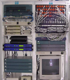
Messy messy messy.....
Pretty, neat, proper, and professional...

|