V-8 Subframe Installation...
Install the new subframe, re-using the origional bolts. Be sure to torque all (6) bolts &
nuts to origional specifications.
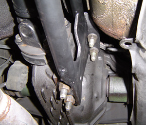
Installing The Steering Rack...temporarily place the rack in position, while carefully aligning & inserting the
steering column’s intermediate shaft into the rack’s input shaft/u-joint.
...When the intermediate shaft is in place, install the rack onto the new subframe,
using the origional bolts (14mm socket w/6”extension), torquing them to origional
specifications.
Pre-Installation Cleaning / Detailing...
...This is probably your last chance to easily detail those places remote and
inaccessible, so take a quick look around before it’s too late.
...Take this opportunity to change the RX-7's fuel filter. There will never be an easier time to do this.
Rigging Engine/Trans For Installation...
...For installation, the engine/trans should be rigged so that they naturally hang
level, or slightly tail down.
Dropping the Engine / Transmission into Position...
...Carefully lower the engine and transmission assembly into place. Line up and install the two 7/16" dia bolts and locknuts
through the engine mounts, pinning the engine mounts to the subframe.
...After the engine/trans are in their approximate position, support the transmission,
with a floor jack or jackstand, with the output shaft centerline about 6-1/4” below the top
of the transmission tunnel.
...Remove the engine hoist and chains.
...Torque the (6) rubber mount/block bolts to 30 ft/lbs.
Torque Arm, Anchor & Transmission Crossmember Installation...
Torque Arm Anchor Bracket Installation...The anchor bracket bolts onto the side of the T-56, on the left side just below the shifter.
 Installing Torque Arm / Differential Adapter Brackets...the torque arm differential adapter brackets bolt onto the existing differential
studs (formerly used to attach the PPF), using the origional RX-7 hardware. The lower
bracket can be identified by it’s use of (2) vertical bolt holes, and an additional horizontal
bolt hole, for a total of (3) attaching holes. The upper bracket has only the (2) vertical
bolts.
Installing Torque Arm / Differential Adapter Brackets...the torque arm differential adapter brackets bolt onto the existing differential
studs (formerly used to attach the PPF), using the origional RX-7 hardware. The lower
bracket can be identified by it’s use of (2) vertical bolt holes, and an additional horizontal
bolt hole, for a total of (3) attaching holes. The upper bracket has only the (2) vertical
bolts.
Installing / Pre-Adjusting The Torque Arm...the rod ends in the rear of the torque arm come installed and pre-adjusted for
proper pinion angle.
...The rod end on the front of the torque arm should be adjusted at the time of
installation, to a length that allows easy assembly of the eye bolt into the torque arm
anchor bracket attached to the left side of the transmission.
Transmission Crossmember Installation...
...12mm wrench
...12mm socket
...14mm wrench
...14mm socket, rachet, and 6" extension
...9/16" wrench
...9/16" socket and torque wrench
4L60E/T-56 Transmission Crossmember Installation...remove the shield that covers the fuel lines on the left side/bottom of the
floor pan, where they pass by the rear of the transmission.
...Install and loosely bolt the rubber transmission mount pad onto the transmission.
...Loosely bolt the crossmember onto the rubber trans mount pad.
...Tighten all the installed trans mount and crossmember bolts. Properly positioned, the
crossmember spans the distance between the frame rails, leaving enough room for the fuel and
brake lines. Re-locating the fuel and brake lines is not required.
...Using a 3/8” drill bit, drill holes in the floor pan thru the (6) holes in the ends of
the trans crossmember (3 holes on each end).
...Install the supplied bolt plates from the top side of the floor pan, thru the new
drilled holes.
...From the bottom side of the floor pan, bolt the trans crossmember onto the bolt
plate studs, using the washers and nuts supplied. Tighten the bolts.
...Remove the floor jack (or jack stand) from under the transmission. The
engine/trans should now be resting on it’s own mounts, and supported by the chassis.
Checking Drivetrain Alignment / Clearances...
...The properly installed Chevy engine is centered in the car. The RX-7’s rear
differential’s pinion flange is offset 3/4” to the right of center. This is normal. The
engine/trans and the rear diff’s pinion centerline should be parallel, but NOT concentric.
If the centerlines were concentric (exactly lined up with each other), the u-joints would
fail prematurely as they need at least slight internal movement to lube properly.
...The assembled driveline & slip yoke can be installed. The (4) pinion flange bolts should be
torqued to 43 ft/lb. At least 3/8” of clearance should exist between all parts of the
driveline / torque arm / transmission tunnel.
Be sure to double check clearances at the...
....Steering rack / oil pan
....EGR valve / firewall
....Harmonic balancer/ sway bar
....Hood / throttle body top etc.
....Alternator
Connecting The Back-up Lite Switch...
...to operate the RX-7's back-up lites, Mazda used a transmission mounted SPST switch to complete the circuit.
When the RX-7's emission harness is removed with the rotary engine, part of this circuit is removed as well.
To restore this circuit, a harness extension will need to be added at connector X-14,
this is a rectangular 2 row 14 wire connector (1 row of 6, 1 row of 8, 2 wires missing) between the "emissions"
and "dash" harness, located under the dash in the passenger footwell area.
2 of the wires in this connector are for the back-up lite switch. These wires are...
...black wire w/ yellow stripe... comes from 15a fuse in underdash fusebox.
...red wire... goes to back-up lites.
Connecting these two wires together w/ a jumper wire will turn on the RX-7's back-up lites when the ignition switch is in the "ignition" and "start" positions.
Routing and connecting these two wires to your new transmission's back-up lite switch will enable the RX-7 back-up lites when "reverse" position of the shifter is selected.
2....Considerations & Requirements....
4....Engine / Transmission Installation....
5....Exhaust / Throttle Cable / Accessory Drive / Pulleys....
6....Cooling / Fuel Systems....
7....RX-7 Wiring Harness Connector ID and Circuit Locations....
8....Electrical System Modifications By Circuit....
9....Start-up / Troubleshooting....