Suspension, Brakes & Steering:
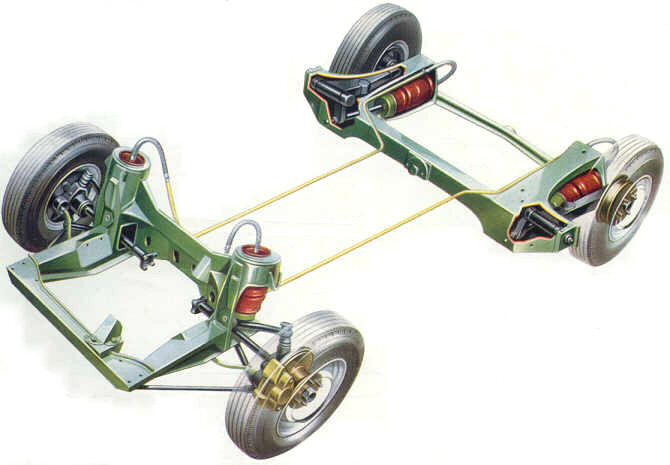
| The Hydolastic Suspension System |
|
|
| The soul of these great cars! |
The Suspension and Brake system on the Americas
can be extremely durable, or extremely problematic depending on the care they receive. Preventive maintenance goes along
way with both of these systems.
Hydrolastic Suspension System:
| Preping for suspension service |
|
|
| The Churchill Hydrolastic machine & Morris fluid |
-The hydrolastic suspension system contains special hydrolastic fluid, a version which
is still available for about $30 for a 5qt. (1 Imperial Gallon) can. I recommend using it if you're going to add to
your system that you consider first completely depressurizing the system completely and then adding new clean fluid.
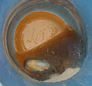
The reason I recommend this, is that the car's system will be full of rust and other crud, as you can see in
the photo below. This is the 33 year old fluid from my own car. I was amazed to see all the rust sediment
in it, after I let the bucket sit for a few days.
-The original fluid is a mixture of water, alcohol and anti-corrosives. I've heard that
it was actually tainted so it tasted bad because the factory workers were drinking it! The new fluid appears to only
be antifreeze and water. It has no alcohol odor as the old fluid.
-I've also successfully used, as have many others, a 50/50 mix of antifreeze and distilled water.
Although I haven't used this for a long time, some people that I know and whom I've talked to, have only used this mix for
decades. All without problems.
-To re-fill an intact system, you'll need just over a half gallon (2 liters) of fluid.
I'm not sure what a completely dry system will take, but I'm guessing close to 3/4 of a gallon.
-The fluid pressure in the system should be 220lbs. and the America's correct ride height is 13-5/8" measured from the
center of the front wheel to the underside of the wheel well opening in the front fender. There is no measurement
given for the rear height, but the car should sit level. If it does not sit level when the proper pressure is reached,
you'll need to look to other sources for that problem.
- Weak or broken rear auxiliary spring(s).
- Excessive wear in the roller feet either at the front upper control arm or rear trailing arm.
- Broken or damaged subframe mounts.
| Rust sludge in 33 year old hydrolastic fluid |
|
|
| Guess what your hydrolastic fluid is doing |
Instructions for using the Factory Churchill Hydrolastic Suspension Pump:
These instructions are taken directly from the placard that is affixed to the
top of my own Churchill Hydrolastic Suspension Pump. This is nearly transcribed word for word, except for the sentence
below highlighted in red, which is my own addition.
To discharge fluid from the displacers:
Fit black connector
to displacer valve with knurled knob unscrewed. Open black valve
on left hand side of unit. Screw knurled knob in fully. When pressure drops to
zero, unscrew knurled knob and remove connector from displacer valve.
To evacuate air from the displacers:
Fit Yellow connector to the displacer valve.
Close yellow valve on right hand side of unit. Operate vacuum pump (yellow
handle) slowly until at least 27 inches of Mercury is held on gauge and movement of fluid has stopped. Open yellow valve on right side of unit and allow pressure to drop to zero.
Disconnect the yellow connector from the hydrolastic displacer valve.
To pressurize system:
Fit black connector to displacer valve with knurled knob unscrewed. Close black valve on left hand side of unit. Open bleeder
valve near the connector attached to the displacer valve. Slowly pump the black
handle until only fluid, not air, is being purged from bleed valve. Close bleed
valve. Screw knurled knob in fully. Begin
pumping black handle slowly to pressurize system. Pump until the system reaches
the proper pressure. Bounce suspension a few times to make
sure that the maximum pressure is still held. Pump in more fluid if needed to
put system at proper pressure. Unscrew knurled knob. Open black valve on left hand side of unit. When pressure
has bled off to zero, remove black connector from displacer fill valve.
Differences In The Displacers:
Below is information on the differences
in the Displacers that were used on the ADO-16 models, from my friend in Greece, and fellow ADO-16 owner, Demetris Bouras.
"In essence, until about 1972-73 all ADO16 displacers are the same, colour coded green.
Front and rear ones (apart from the obvious valve difference) had a different knuckle joint connecting rod, short at the front,
long at the back, but these are interchangeable. The blue coded ones were having only a slightly longer rod, to compensate
for the heavier transmission of the automatic cars. The last cars had displacers with stiffer internal valves and were coded
orange.
That's all."
Demetris
Building your own hydrolastic suspension pump & service
tools:
Pressure Gauge:
| Pressure test gauge |
|
|
| Easy & inexpensive to make |
-You can make a pressure checking gauge like this one for about $15. I combined the 300lb. gauge
with an angled tire fill fitting. You can get both pieces at NAPA auto parts stores here in the U.S.A. under the following
part numbers:
- 300lb. Gauge: 2" dial face, 1/4" pipe thread fitting, #701-20-10 or 701-2010.
- Angled Chuck: Nickel or Brass finish, 1/4"pipe thread, #90-523.
These can also be found at other sources like industrial equipment suppliers, etc.
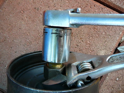
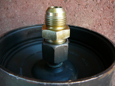
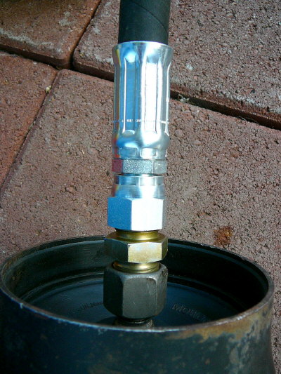
Hyrdolastic Suspension Pump:
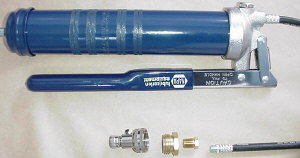
| Hydrolastic Suspension Pump |
|
|
| Hydrolastic fill valve with adapters. |
|
|
-I learned about the tractor tire fill valve trick from my friend and long time British car
mechanic Peter Jergens. Peter owns "British Sports Cars" here in San Luis Obispo and has been using his homemade
grease gun/tractor tire fill valve pump for years. I've borrowed it several times.
Now, thanks to a great tip from Don Cameron in Canada, who sent me an email and photos of
the hand pump he'd just built after visiting my site, these assemblies are even easier to make.
Don used the Tractor Tire fitting from NAPA, part number 90-234. He then went to a Hydraulic
shop that sold him a brass fitting that adapted from the garden hose threads on the Tractor fill valve to the 1/8th inch pipe
threads on the grease gun flex hose. He says it fit and worked perfectly. The brass adapter was $3.
Nice solution Don, thanks!
I made my own grease gun using Don's method. I couldn't find the same adapter that Don
used, but with an additional brass "bushing" I was able to step down from 1/4" to 1/8" pipe threads. Again, about $3
for the adaptors and $18 for the Tractor tire valve.
I spent a total of $55 to make this pump out of all brand new parts.
NOTE:
Many users of the grease gun fill method have complained that it takes too long and leaks
a lot of fluid. One of these folks decided to try an air powered grease gun (you'll need an air compressor) and
wrote back to say that it worked fantastic and pumped the car up in literally seconds.
Using the grease gun style pump:
-You can screw this Tractor Tire Valve fitting onto a standard cartridge using hand
pump style grease gun with an 18" flexible hose. To use, simply remove the end cover on the grease gun,
as if you were going to install a cartridge, turn the gun nose down, and pour the Hydrolastic fluid into the gun.
50/50 anti-freeze and water can be used in lieu of actual hydrolastic fluid, which is still available. Leave the end
cover off the gun and keep it turned nose down during the pumping procedure. Basically, the gun is acting as a funnel
at this point.
Pumping up the Hydrolastic system:
-If the Hydrolastic system has been opened up for any reason, it will have air inside which
must be removed prior to pumping up. To do this you'll need to hook up a vacuum pump and pull the system
under a vacuum. Either an electric vacuum pump or a venturi style pump that operates on air from your air compressor
will do the job. Once the system has been evacuated, it can be pumped up.
-Harbor Freight sells an air powered vacuum pump for about $10.
-If you don't want to mess with evacuating the system, here's what to do: Loosen the
hydraulic hose fitting that is located just below the floor of the trunk. To access this fitting, remove the cargo floor
in the trunk and you'll see two oblong rubber plugs that are pressed into the sheetmetal of the car's trunk floor.
These are located up on the "hump" where the trunk floor curves up and over the rear suspension. Removing the
plug(s) gives you access to the hydraulic fitting that connects the suspension hard pipe(s) with the rear displacer(s).
Crack this fitting open. Begin filling the system as you normally would. As you are filling, wait for fluid to
start to be expelled from the loosened rear fitting. It's sort of like bleeding brakes, and once the rear fitting
is leaking, snug it up, and fill the system completely. Once the system is full, bleed off some pressure. This
should blow out any remaining air. Top the system up and you should be good to go.
-If the Hydrolastic system has not been opened up, but one or both sides are low, you don't
need to evacuate the system. Unless you are unsure if someone may have had it opened at one time. For example,
a car that is just low because a previous owner thought it would be a good idea to lower the car by simply releasing system
pressure. This car won't need to be evacuated. Or a car that has been sitting for a number of years and
is "down" on one or both sides. This car won't need to be evacuated either.
-To fill the system, screw the Tractor Tire fitting onto one of the car's schrader valve service
ports on the flexible hoses that come up out of the front Displacer Units. Fill the grease gun about half
way up with fluid. Now depress the bleeder valve on the Tractor Tire fitting and slowly pump the grease
gun handle until fluid runs out of the bleeder. Now you know you won't be pumping air into the system. Release
the bleeder and continue slowly pumping the grease gun handle. Pump up each side of the suspension (if you are raising
the entire car) alittle at a time. Rock the car once in a while to help the suspension settle. Continue pumping
until the suspension is to the correct pressure and height: 220psi and 13-5/8" from the center of the front wheels
to underside of front wheel wells. There is no measurement given for the rear wheel well heights, but if the rear is
sagging, you'll need to adjust or repair the 2 auxiliary springs fitted to the rear subframe. Your manual will give
details on making the rear height adjustment.
An alternative Hydrolastic Suspension System Fill Valve:
-If the Tractor tire fill valve is not available in your area, here's a solution.
This actuall fitting was given to me by a former British car mechanic who used to work on the 1100's in England. He
told me this is the fitting he always used with the grease gun style pumps.
It is simply a grease nipple, or zerk fitting, threaded into a metal shrader valve cap.
That's it!
| Hydrolastic Suspension Fill Fitting |
|
|
| Alternative fill valve |
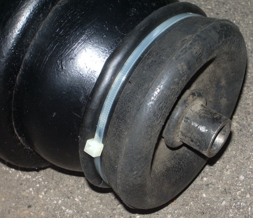
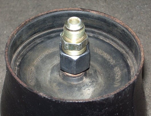
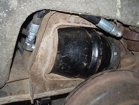
Re-hosing the hydrolastic displacers:
There are rubber reinforced hydraulic hoses that are crimped onto the fitting
that rise out of the tops of the Hydrolastic Displacer Units at the front and the rear of the car. If the hydrolastic
suspension system's rubber hoses fail, all is certainly not lost and there is absolutely no need for panic.
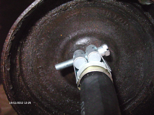
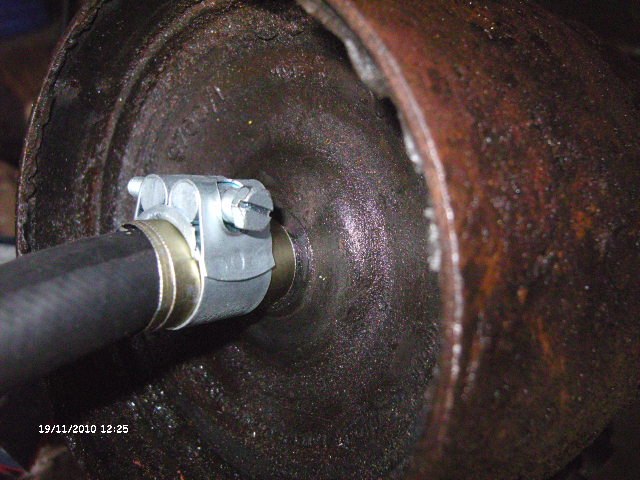
METHOD #1
Here is the latest method to re-hose the hydrolastic displacers.
This was sent to me by Gordon, a fellow ADO-16 owner in Europe the UK.
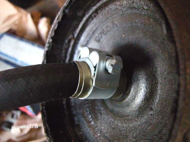
Gordon has come up with an ingeniously simple repair method, and the photos below speak volumes!
Visit the clamp manufacturer's website at http://www.pirtek.co.za and you'll be ordering stainless steel heavy duty hose clamp number: IHCTS17-19 (17mm-19mm size range)
or IHCTS19-21 (19-21mm size
range)
You'll need to measure the diameter of your new hydraulic hose to see which hose clamp will
work best for you.
The photos show this special German made hydraulic hose
clamp being used. The brass banding that you see around the hose, beneath the clamp, was put there to give the clamp
more of an ability to crush the hose tight.
This repair is so simple, it may be able to be completed with the displacer still in the car.
Like my method below, the old banding clamp and the original hose are cut off the fitting
that's bonded into the displacer. The new hydraulic hose is pushed on, and then this special clamp and the brass shim
stock, are slid down and tightened.
METHOD #2
This method was sent to me by Ian Gaffney, London, England, on Oct 27, 2014.
Ian made these clamps himself, and they are a work of art. I'm very honored to have received 2 of them...but I hope
I never need to use them!
METHOD #3
This method works for the front Displacers, since there is ample clearance
for the straight hydaulic hose and new fittings to rise up out of the top of the Displacer.
A modification to this method is best used for the rear displacers, and is listed
below.
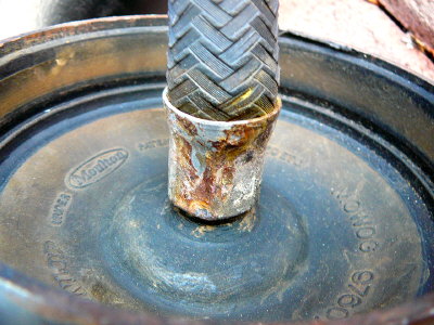
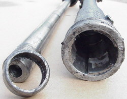
| Old displacer hose |
|
|
| This is how it looks prior to repair |
Here is the method I use to re-hose the hydrolastic displacers. Below my method, is
a method that works equally well.
-Remove the displacer from the car. The photo to the left shows what the original hydraulic
hose looks like prior to starting this repair.
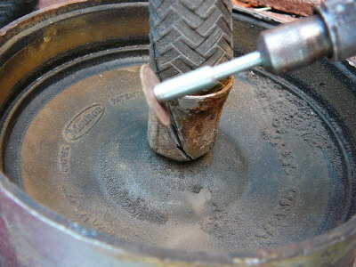
| Cutting through the banding clamp |
|
|
| Cut like this using a cut-off wheel |
-Use a die-grinder or dremel tool with a cut-off disc and slice the metal banding clamp at
the end of the hose.
| Remove the old banding clamp |
|
|
-Use a pair of side cutters or wire cutters to pry the cut on the banding clamp open, and
then remove the hose and the banding clamp.
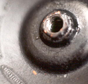
| The original fitting looks like this |
|
|
| These are the 3 new fittings you install |
|
|
-Purchase and install one each of the following fittings:
“Metric Flareless
Tube Sleeve”……………………...7165x14
“Metric Flareless
Tube Nut”………………………....MH7105x14
“MJ – Metric Tube Seat
Hydraulic Adapter”………..MC5208x10x14
-If you are working
on the front displacers, you will need this special banding clamp in order to install the old fill fitting into the new hydraulic
hose.
“Gates Hose End Ferrule”……………………………8PC1FS
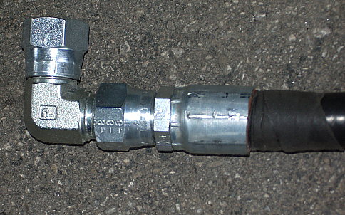
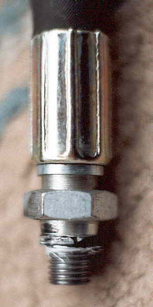
| Install the new fittings tight |
|
|
| Here is how the new fittings look installed |
|
|
| All ready for the new hose |
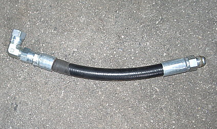
| New hydrolastic hose installed |
|
|
| Ready to go back into the car |
-Visit your local
industrial/hydraulic repair shop and have them make a new section of hydraulic hose to match the hose you removed.
-Tighten that new hose into the new compression
flare fitting that you've installed on the displacer.
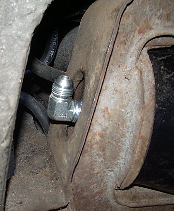
-Install the displacer into the car and
fill the suspension system, bleeding it as needed, and then topping it off to the correct pressure and front height measurement
as per the manual.
METHOD #3 for Rear Displacers:
A huge thank you to my friend and fellow America owner,
Mark Margetts. Mark recently had a rear Displacer hose fail, and developed a modification to the "Method #3" repair
after we discussed that there might not be enough clearance for the new hydraulic hose and the somewhat tall stack of modern
hydraulic fittings.
Mark was kind enough to send along the following photos.
METHOD #4
A huge thank you and a big pat on the back goes out to my friend and fellow
Austin owner, Demetris Bouras of Greece. Demetris created this method for repairing Displacers back in the late 90's,
before anyone else had come up with a method. He was kind enough to provided the detailed instructions below, and has
successfully repaired his own Austin in this manner.
I don't think it's really complicated to repair the displacer
but your
hydraulic shop should have a straight (not angled) grinder and a lathe. As you said the original hose is crimped
into a pipe about 25mm long that comes out of the displacer. Due to the position of the crimping point in a deflated displacer
it is not possible to crimp a new hose in the original way.
However you can overcome this. First, using the grinder
cut the old crimping ring to remove the old hose. You should continue with the grinder to cut the pipe coming out of the displacer
about 2mm above the rubber. Then you can do an internal thread to that pipe. As you can see from the relevant photos it goes
deep enough to the displacer for that. In my case I used 12mm/1.5mm parallel thread. If you want to, you can experiment
with finer and/or tapered thread for better sealing properties. However I have never had any sealing problems using teflon
tape and some paint.
As there is not much possibility in finding off the shelf an adaptor for the suitable hose size and with the right
thread you have to convert something using the lathe. If you are repairing a front displacer the hose to displacer distance
is not critical and you can make the adaptor as in the photo to simplify the bolting to the displacer. However, in a rear
displacer that distance is critical and if much greater than standard you may find that the hose is rubbing the subframe.
In that case you should extend the adaptor thread up to the hexagon.
Then it's a simple matter to crimp the new hose to the adaptor and to the union off the old hose, and to bolt the
new hose to the displacer, using some teflon tape and some paint.
cheers,
Demetris Bouras
Greece
| Cut Displacer hose fitting off 2mm above rubber |
|
|
| Then thread inside of remaining fitting |
| Have hydaulic shop build hose w/ fittings |
|
|
| This is inexpensive |
| Mount new hose to Displacer |
|
|
| Using teflon tape or paste as thread sealant |
Suspension Noises:
If you have rattling or clacking sounds when driving
over bumps or uneven surfaces, here are some of the common sources.
At the front:
- Check out the shields on the front rotors by kicking the front tires.
- Jack up the front and check for loose and missing bushings for the lower control arms. Check the bushings at the
front radius rods. High quality urethane front suspension bushings are available from sources like Seven Enterprises.
Just ask for Mini MK 2 front suspension bushings. They are a perfect fit and easy to install.
- Check the radius rods where they connect to the lower control arms. The bolt holes get wallowed out and you'll get
a lot of slop there.
- Check the bushing in the passenger side of the steering rack by grabbing the passenger side track rod and lifting it up
and down. If you can feel play, the bushing is bad and needs to be replaced. They are still available from the
UK and I'm currently working on having them reproduced here locally. Replacement instructions are listed below in the
"Steering Rack" section.
At the rear:
- Check the brackets where the parking brake cables go through the backing plate. If the lower rear brake shoe spring
isn't put on correctly, to have it's little foot pressing down on the parking brake levers, you'll get a ton of clanking and
rattling when you go over bumps. The parking brake levers rattle like crazy against the backing plates.
- Jack the rear up and try to push and pull the wheel out of the fender. Do this in a way that will push and pull
on the rear trailing arm, because you may have failed trailing arm bearings and the arm may have a bunch of slop in it. The
1100 bearings aren't able to be lubed like the ones on the Mini.
- While it's off the ground, check the condition of the 2 auxilary springs that act like torsion bars and go from the trailing
arms to the center of the front of the rear subframe. They break where they turn and go through the subframe. Also,
if your car has a rear sway bar, check that it's held securely.
- Lastly, check the exhaust system for banging against the underside of the car.
Brake System:
The biggest enemy of the hydraulic system in a British car is infrequent use and storage. The second enemy is water. Since
brake fluid is "hydroscopic" and absorbs water, the rubber and metal parts of the system can really suffer.
-If you are going to use conventional brake fluid, ie, DOT3 or DOT4, then change and flush it every 2 years. Most people
recommend Castrol Girling LMA brake fluid for British cars due to the type of rubber used in the system.
-I
switched mine over to DOT5 Silicone back in 1998 and haven't had any problems since.
-If you switch to DOT5,
make sure you flush the system extremely well with the DOT5. The combination of DOT3/4 and DOT5 will attack the insides of
the flexible rubber hoses in the brake (and clutch) system, causing the hoses to swell shut inside.
Rear Brakes:
| Rear Brake Assembly |
|
|
| This is how the springs and shoes go |
Brake Flex Hoses
- I can't stress enough the importance of installing new brake flex hoses. There are 5 of them:
One at each front caliper, one at the front middle section of the rear subframe, and one at each rear brake drum.
These rubber hoses rot inside and the rubber turns into a black muck. When this happens, the hoses will either partially
or completely swell shut. This results in either a "check valve" type of brake operation or a false good feeling pedal.
In the check valve typ condition you can step on the brake pedal and force fluid out to the brake(s) through the partially
collapsed hose(s), but the fluid can not be returned when you take your foot off the brake. This causes the brake(s)
to drag and overheat, and it causes dangerous brake pull as one brake is usually held on more than the others. In the
false good feeling pedal, the brake hose(s) will be completely closed off internally and no brake fluid is making it out to
the brake(s). So the pedal feels fantastic, nice and firm, but you can have both rear brakes (for example) not
even functioning.
- It is a waste of time and money to think that 40 year old brake hoses are still good. No matter
what you think, or feel in the brakes, the hoses are not good. Additionally, even if they are currently appearing to
be okay, if you actually removed them and blew through them compared to blowing through new brake hoses, you would discover
how bad they have become. The hoses are very inexpensive, take very little time to replace, provide 100% improvement
in brake function and the safety of the car, and will last for decades, especially if you are switching to DOT5 Silicone or
the new synthetic brake fluid. Don't kid yourself in thinking that your old unknown hoses are "okay."
Rear Wheel Cylinders
- The Austin America uses the same rear wheel cylinders as the early MGB. They are
inexpensive at around $30/pair and readily available. The only difference being that the locating pin on the back of the
MGB cylinders in on the opposite side, so you'll have to drill a small hole in the backing plate to accept it. If your
old wheel cylinders are still worth rebuilding, use the kits for the MGB, at about $7ea.
Rear Brake Adjustment
- Keep the rear brakes and the parking brake adjusted correctly. When out of adjustment they cause an extreme
amount of pedal travel and give the feeling that the Master Cylinder may be going bad. The proper way to adjust the
rear brakes is to tighten the adjuster, located at the top of the backing plate, until the wheel is locked. Then, back
off the adjuster just until the wheel can be turned again without a lot of brake shoe dragging. You'll feel it
when it's right. The adjuster has an "over center" cam shape, so as you turn it, you'll feel it get difficult to rotate
and then easy to rotate and then difficult...then easy...etc., etc. If you don't feel this, you should pull the
drum off, clean the adjuster and put some anti-seize compound on it. Then it will work properly and allow you to adjust
the brakes correctly. Ideally, you want the rears tight without dragging.
Parking Brake Adjustment
- The parking brake is adjusted by turning the knurled knobs on either side of the parking brake handle.
The manual says to lift the rear of the car, pull the handle up 4 clicks, then turn the knurled knobs until the rear wheels
are locked. I disagree with this because it puts a lot of wear on the over-center heels of the knurled knobs.
I prefer to lift the rear of the car, and with the hand brake released, turn the knurled knobs until the rears are locked
at about 2-3 clicks when you pull up on the brake lever. This gives a much better feel at the brake pedal.
- If your brake shoes get soaked with brake fluid, install new shoes! Brake fluid
soaked shoes, even if you try cleaning them, are ruined and dangerous! They don't grab right away when you apply the brakes
because the fluid in them acts as a lubricant until it heats up...then, once hot, it causes the shoes to grab and lock
against the wheel. With one rear wheel locked during braking you have an excellent chance of doing a 180 degree turn. Can
you guess how I learned this lesson?
Removing the rear brake drums
- To remove the rear brake drums requires a puller because they are drawn onto the rear wheel bearings as the
center axle nut is tightened. First loosen the center axle nut so that it is flush with the end of the rear axle.
Remember, the left axle nut is reverse thread (so that it doesn't come loose during the forces of stopping the car).
Next, take the dished metal plate off the spare tire hold down in the trunk and place it.....dished face inward.... resting
on the axle nut. Now put the wheel back on, and evenly tighten the lugnuts. This will force the wheel against
the dished plate and as you tighten the lugnuts, the brake drum will be pulled off. During this process you'll
have to reach in and continue to spin the axle nut back out to give you more leverage with the dished cup, and allow the brake
drum to slide further off. I didn't make this up, it is noted in the Haynes BMC 1100/1300 Service Manual.
Rear Suspension System:
-The rear of the car gets additional lift and support from 2
torsion bars, called "Auxiliary Springs," mounted in the front cross member of the rear subframe. The springs help
keep the rear of the car from sagging and help with the bounce rate of the rear-end. They are shaped like
long "L's". One end of the "L" is ground square and fits into a squared opening in a bracket which is bolted to
the rear trailing arm. The ohter end pokes through the front cross member of the rear subframe where a nut hold it and
a bushing in place.
Your manual talks about being able to adjust the rear height of the car, so I won't get
into that here as it's pretty simple.
However, because these "springs" have to constantly withstand twisting forces, they are
prone to breaking. Maybe more so on the 1968 and 1969 cars due to increased rust. So, you may want to check that
yours are still intact, or even on the vehicle.
If you need to replace one or both, the job can be done fairly easily and without depressurizing
the Hydrolastic system and removing the rear subframe as the manuals suggest. Here are the steps I took to replace one
"spring."
Here's the method I used. I did the installation in about an hour without depressurizing
and without removing the subframe.
- Jack up and support the rear of the car and remove the wheel.
- Bend the tabs away from the 2 bolts that hold the Aux Spring to the trailing arm.
- Jack up the trailing arm by putting a jack under the brake drum.
- Loosen both bolts, but only remove the front-most one. (This allows the bracket that
takes the square end of the Aux. Spring to be swiveled and angled as needed.)
- Lube the square end of the Spring and push it all the way through the bracket.
- Install the other end of the Spring through the opening in the center of the subframe and
thread the big securing nut on by hand.
- As you're doing this, the square end of the spring will be pulled back into the squared
opening in the afforementioned bracket.
- Use a large screwdriver with the tip place against the inner pivot bolt of the trailing
arm. The shaft of the screwdriver will now be against the bracket.
- Pry the bracket up so that the front-most bolt can be re-inserted and it will thread in
by hand if you put a bit of spray lube on the threads.
- Once you have the 2 big bolts threaded up by hand move to the outside of the car.
- Snug up the bolts just barely because you want the bracket to still be moveable.
- Put your screwdriver back in place in the prying position and really lift the bracket.
- Put a jack stand or a floor jack, etc. under the handle of the screwdriver to hold it in
the prying position.
- Tighten up the 2 big bolts and bend the lock tabs up.
- Tighten the big nut at the center of the subframe where the Spring pokes through.
- Put the wheel back on and you're done.
I descovered that if you tighten the 2 big bolts without prying up on the bracket and
without having the trailing arm compressed, the Spring will have increased leverage and want to lift that corner of the car.
So, re-doing that portion of the job took another 20 min. or so to figure out a way to hold the prying action while
tightening the bolts.
Front Suspension:
Solving Front
End Vibration/Shimmy:
I thought I'd share some
info on how I've finally solved my ongoing vibration in the front end of my America.
A bit of background is that I've had the car 20 years and it's
always had a vibration at certain freeway speeds. From about 55mph on, it would come and go. Better at some
speeds, then worse at others. I have always attributed it to the poor build quality and/or bad condition of
the factory steel wheels and to me buying cheap tires.
A couple years ago I tackled the wheel problem and went through
about 12 just to get 5 that were good enough to powdercoat and use. I got some improvement, along with buying a
set of Dunlops and holding the tire guy's hand while he mounted and balanced them. Our "joint effort" included
rotating the tires on the rims to get the least amount of required balance weight.
Since the problem wasn't going away, I decided it was time
to jack up each front wheel by the lower control arm and watch what the axles, inner U-joints, brake rotors and hubs were
doing. The reason for jacking up by the lower is to keep the suspension and axle geometry as close to the actually driving
geometry as possible.
I found one inner axle flange bent and causing the axle to wobble
quite a bit. I replaced it, the axle stopped wobbling, and got more improvement, but the vibration was still present.
I then spent over an hour at the local Dunlop dealer (in
order to determine whether I had a set of bad tires. We spun, rebalanced, dismounted swapped, you name it....to all
the tires. I was amazed to see the same tire wobble and need 4oz. of weight in one position on the rim, then rotate
it 180 degrees and it would smooth out and need only .75oz of weight. This seemed to help a little, but still not
perfect.
So, I again jacked up one side at a time and watched everthing
spin with and without the wheel on. At 75mph the wheels were hopping all over the place. With the wheels off,
the hub, rotor, axle, everything were all nice and smooth.
It was then that I finally noticed the hub area of the
brake rotor, where the seperate flange bolts up (the wheel bolts to this flange). The hub area of the brake rotor was
pulsing......out of round. But, as I said the actual brake disc area and the flange were perfectly straight. It
was like the hub portion was cast offset and then the rotor was machine back to true.
I put on a set of NOS rotors that I've had and the problem is
cured! The rotors that were on the car are its originals and I'm guessing the car was probably like this from the factory.
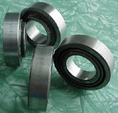
| Above New style front wheel bearings |
|
|
| Below Original style front wheel bearings |
-Good News: Since the Austin America uses the same C.V. Joints
as the Mini Cooper "S" and all the later Mini's, it also uses the same front wheel bearings!
-This is important to know because not only does it make finding
and replacing the front wheel bearings easy and inexpensive, it also means you get yet another "upgraded" part.
-I recently replaced a set of front bearings and below are the
steps I took. Hopefully this will help make the job easier for you. Additionally, I ordered a "Front Wheel
Bearing Kit" from Seven Enterprises here in California. $39 plus shipping. This includes the new style one
piece bearings that have the offset inner race. So, you'll no longer have to fight the spacer ring that used to go in
between the original front bearings.
Here are some things to consider prior to doing this job.
- What condition is the outer C.V. joint and boot in?
- What condition is the inner U-joint and flange boot in?
- Is there a leak from the differential side cover gaskets or seals?
- What condition are my lower suspension bushings in?
- What condition is my steering rack boot in?
- What condition is my steering rack tie-rod (track rod) end ball joint boot in?
- What condition are my ball joints in?
- What condition are my brake pads in?
Because you will have the entire suspension nearly torn apart for this job, you might as
well do it all while you're in there.....time and money permitting, of course.
This is an excellent time to install new poly-urethane suspension bushings, semi-metallic
brake pads, and do other upgrades and preventative maintenance.
Also, you'll need a 1-5/16" socket, a big "breaker bar", a torque wrench that goes to 150ft/lbs.
and a real ball joint splitter. A 32oz. ball pean hammer would be nice too.
-Here's how I replaced mine:
- Loosen the lug nuts and the 1-5/16" axle nut. Jack up and support
the car on the side you'll be working.
- Decide if you'll be replacing the outer C.V. boot and serviceing the
C.V. Joint while you have this all torn down. (Recommended)
- If you're going to service the C.V. Joint, then undo the inner U-joint
coupling.
- Remove and support the brake caliper.
- Remove the axle nut and the tapered washer.
- Remove the top and bottom ball joint nuts.
- Using a ball joint splitter and seperate both the upper an lower joints from the control
arm. DO NOT USE A "PICKLE FORK" TYPE SPLITTER NO MATTER WHAT ANYONE HAS TOLD YOU!!!!!!!!! Buy a proper
ball joint splitter. They are about $40 at Seven Enterprises or Heritage Garage here in California and are one of the
best tools you'll ever own. Seriously!
- With the ball joints loose, lift the hub assembly off the control arms and slide out the
axle.
- Take the axle completely out of the car.
- Put the hub assembly back into position on the control arms.
- Remove the brake rotor(disk)/hub assembly. It's just sitting
there at this point.
- Take a large screwdriver and pry both the inner and outer grease seals
out of the hub assembly.
- Pop the retaining ring out from in front of the inner bearing.
It's hiding in a groove just behind the inner grease seal. A wipe down with a rag will help you see it easier.
- Time to drive out the bearings.........Use a big hammer and a drift,
or a 3/8" socket extension, etc. Drive out both inner races and then take out the spacer ring. The inner bearing's
race is tapped out from the outside (the car body side) of the hub assembly. The outer bearing's race is tapped out
from the inner fender side of the hub assembly.
- Now do the same thing with the inner races of each bearing. There are
a few cut-outs in the inner part of the hub assembly. Again, a wipe with a rag will help you find them. Place
your drift in these cut-outs to get a good bite on the inner races. Drive them out in the same directions you drove
out the inner bearing races.
- Pack the new bearings with good quality grease.
- Putting it all back together is an easy reversal of these steps.
Use the old bearings as a driver to drive in the new bearings. NEVER drive bearings into place by they're inside races.
ONLY strike the outer race!!!!!! Wear Safety glasses!!!
- Torque the axle nut to 150ft/lbs., then continue to rotate it until
the nearest hole for the big cotter pin lines up.
A couple of things to mention.
- You may find it easier to just remove the hub assembly completely,
since the top and bottom ball joints are undone and its only held in place by the steering rack tie-rod at one point.
It's up to you. This is just the method I chose because the suspension was a convenient "holder" while I drove the bearings
out and the new ones back in. It just seemed faster to me.
- When you try to push the C.V. Joint spindle back through the new bearings
it's going to be tight and it won't go all the way through. Leave the brake rotor assembly off. Get the spindle
through as far as you can (put some lube on it, right!) and then thread on the axle nut. Use a large screwdriver
or pry bar to pry against the hub assembly and the underside of the axle nut. This will drag the spindle outward.
Keep doing this by threading the nut down as you need more leverage. Eventually, you'll be able to place the brake rotor
assembly on and get the axle nut started without the tapered washer in place. Now, tap on the center of the brake rotor
assembly with your big hammer, while tightening the axle nut. Eventually, you'll get the spindle through far enough
to fit the tappered washer under the nut. Then you're home free.
- Finally, CHECK YOUR WORK!!!!!!!!!
This is suspension, brake and steering component work. If you leave something loose, or something fails, you
could easily lose control and crash, killing yourself and who knows who else!!
Excessive Front Bearing Play:
If you have a car with quite a bit of play in the front wheel bearings, it may not be the front
bearings at all!
Jack up the front wheels and grab them with your hands at the 6 & 12 O'clock positions.
Try rocking the wheel in and out. If you feel any play at all, look on the back side of the wheel and see if it's coming
from the upper and lower ball joints.
Do the same test by grabbing the wheel at 3 & 9 O'clock. If you get any play, check
the steering rack track rod end and the rack bushing (if the passenger side does have play).
Finally, do the same test with your hands in the 2 & 8 O'clock positions. Again, if
you feel play, look on the back side and see if it's suspension related.
Here's what I came across recently while rebuilding the front end in a 1969 America:
- There was a ton of play in the right (passenger side) front wheel. No matter where I
put my hands, there was play....and a lot of it!
- The steering rack bushing was blown out....fixed it.
- The track rod end was bad....replaced it.
- The upper and lower ball joints were wiped out....rebuilt them.
Still, I had a ton of play in the wheel, but now it was much less and it was narrowed down to
where I could watch the CV joint wobble in the bearings as I rocked the wheel. So, eventhough the wheel bearings were
nice and quiet, I replaced them. Guess what? No change in play!
I started thinking about how the front wheel bearings are preloaded. Basically, the axle
nut is torqed to 150ft/lbs and this crushes the inner flange on the hub that the wheel bolts to against the inner race of
the outer bearing. The flange of the CV joint is curshed against the inner race of the inner bearing. Finally,
this crush action crushes the inner faces of the inner bearings against each other and pulls the bearings against the outer
races. Pretty straight forward.....or so I thought.
Here's what I tried in an attempt to fix the problem:
- My initial thought was that I had a warn hub flange. I replaced the flange....no change
in play!
- Okay, maybe the flange on the CV joint is bad. I replaced the CV joint....no change!
- Cone shape washer bad? Replaced....no change!
I finally decided the only thing it could be was the big hub assembly that the bearings are
driven in to. The hub has a shoulder machined inside to catch the outer bearing races and hold them, while the inner
races are free to be crushed into each other a certain amount. I thought, "What if that shoulder was machined to narrow,
so the bearings are too close together and that keeps the inner races from being able to move into each other enough to properly
preload the bearings.
Well, sure enough. I took out the outer bearing and had a machine shop mill .005" off
the inner face of the inner race. That made quite a bit of difference but there was still some play. I removed
the bearing a second time and had an addition .005" taken off.
Perfection (but let me tell you how sick I was of taking that front assembly apart)!
C.V Joints & Boots
-Here's some info that may help in locating outer CV
joint boots for your car.
If you don't already know, our outer CV joints are the same
as the Mini Cooper "S" and "late Mini" joints. Therefore, both the joints and boots or boot kits are readily available.
However, the boot kits here in the USA are quite expensive: For example, $49ea for the OEM Unipart ones from one USA based
Mini parts vendor and about half that for the "generic" ones.
My friends who own the local Brit car shop, British Sports
Cars, here in San Luis Obipso, just showed me that the inner boot for a 1990 Suzuki Swift with automatic transmission
will also fit perfectly. I've installed one and sure enough, it fits perfect. They are $8ea for the entire
boot kit.
*Note: I've used quite a few of these alternative boot kits and they have always
worked fantastic. I highly recommend them!
Remember that when servicing your CV joints, if you find some minor pitting or wear on
one side of the "tracks" that the balls run in, you can swap the joints, left to right on the car and continue using them.
The balls will then be "loading" undamaged areas of the joint and you can get a few more years worth of life out of them.
Of course if they are heavily pitted and worn in the ball tracks they should be replaced
as this causes them to "click" in tight turns and they may also vibrate under the load of acceleration. You'll
have to use your good judgement based on the amount of wear you find and the type of use your car gets.
Remember to put the axle nut on the axle threads (on the end of the CV joint) before making
the mistake of beating on the axle to drive the joint back onto the stub axle. If you screw up the threads on the end
of the outer CV joint, you'll be very unhappy!
My prefered method is to thread the nut down almost flush with the end of the axle, then place the
stub axle splines into the CV joint. Then put down a sheet or two of cardboard onto the concrete. I then turn
the assembly so the axle nut is facing down, with one hand on the stub axle and one hand on the CV joint. I drive
this down onto the carboard/concrete......pile driver fashion. Usually on the first strike the stub axle's wire
circlip hangs up. A thin straight bladed screw driver can be use to "tuck" the sides of the circlip back into
place while it's still sort of pinched from the impact. Then, another couple of wacks will drive the stub
axle all the way into the CV joint.
Also, to do a neat job on the metal CV boot clamps, you can buy the proper crimpers at places like
NAPA or Sears and they're not that much money. In a pinch you can also use "end cutters" or "side cutters" (some
people call these types of wire cutters "dykes"). But the proper crimpers are a great tool to add to your collection!
Messy job, so wear your blue nitrile mechanics gloves and keep the shop towels flowing!
Steering Rack:
-The steering racks have a bushing on the passenger side which will fail after time as it
was probably originally felt. When it fails you'll get a loud metallic clunk when going over bumps.
NOTE:
The original "updated" steering rack bushing, part number BTA-0795, is no longer available
as of this Oct. 2014 update. The latest and best option for repairing the steering rack is to purchase the "nolathane"
steering rack bushing that's being sold in Australia, for the Mini. These are much longer than the original band shaped
bushing, and have a polygon shaped inner opening where the rack slides. Quite a few Austin America and MG 1100 owners
have installed them, and are reporting excellent quality, and fit, and a definite cure to the problem. Link: http://www.eziautoparts.com.au/steering-rack-and-pinion-internal-bushing-41039.html
-To check for a bad bushing simply grab the left tie rod (called a track rod in the manual)
and give it a tug up and down. You'll feel it move about a 1/4" total and it will clank!
-The rack can be removed with the engine and subframe in the car. The subframe does not have
to be lowered in the rear as the manual states.
-Here are the basics.
- Remove the steering wheel competely since it's just held in by two bolts
once the pinch clamp
bolt is off. Hint: to seperate the pinch clamp, tap in
a slotted screwdriver to act as a wedge and spread the clamp.
Then sit in
the front seat and pull up on the steering column via the steering wheel. I
like to turn my head
sideways so that when the steering column comes loose I
don't knock my teeth out or break my nose with the steering wheel....but
I'm
funny that way.
- Next, jack her up, remove the front wheels, pop the track rod ends off .
- Next, remove the 4 nuts on the firewall under the carpet that hold the "U"
shaped clamps in place
for the rack. The rack is now free. Crawl under and
remove the "U" shaped clamps and the their flat brackets
from the rack.
- Now work from under the driver's floor. Rotate the rack to remove the
splined pinion from
the hole in the floor. It will hang up on the suframe at
this point. I big screwdriver will pry it easily
past the subframe with very
little effort.
- Now work from the driver's wheel well next to the car. Use your big 3' long
pry bar and
push the firewall near where the rack's splined pinion (where the
steering column attaches) toward the interior of the
car. The firewall is
very flexible and soft, so it doesn't take much effort to push the firewall
in about 1/4"
in this area. And, you'll easily be able to flex it back into
position upon re-assembly.
- With the firewall moved inward a bit, the rack will twist a bit more and you
can pull it out from
the driver's side. No big deal.
- Unfortunately getting the bushing out requires nearly complete disassembly of
the rack.
You have to remove the passenger track rod completely. The manual shows two special tools for doing this. I don't
have them and was able to carefully use a large pair of curved jaw Vise Grip brand pliers. (If you don't have Vise
Grip brand pliers, get some. Any other brand is very inferior and your results will suffer.)
- Knock indentation up on track rod lock collar. Then loosen the collar using Vise Grips.
Use a second set of pliers to hold the track rod ball end as you turn the lock collar in the opposite direction. Once
the lock collar is loose about 1/2 a turn, you can take the track rod completely off. Then remove the lock collar.
- Now you have to remove the pinion gear and tensioning bush. You don't have to take apart the
driver's track rod or remove it. Keep the shims as you'll be putting it all back together the same way the factory had
done.
- With the rack taken this far apart, you can slide the rack out of the
housing.
- Now it's time to drive the bushing out from the inside. I found a screw
driver handle that
was just the right size to fit through the housing but
wouldn't fit through the bushing. I dropped it into the housing
and hammered
it and the bushing right out.
Warning!! A failure of the steering rack could potentially
cause a terrible crash, killing you and others. Read your manual before and during this repair....or any repair on your
car for that matter. If you don't have a manual, get one. They're all over ebay. Do a search for "Austin
1100" or "1100/1300". Make sure you reassemble the rack according to the manual's instructions.
Also, make sure you fill the rack with "Extreme Pressure 140w Oil" (EP 140W). It holds
.4 Pints. That's just under half a pint, so about 7 ounces.
| Steering rack disassembled |
|
|
| Note bushing collar with no bushing material left inside |
| Currently available bushing |
|
|
| Bushing is made of nylon |
|