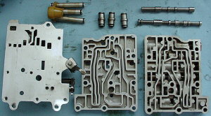
| Exploded View |
|
|
| The internals are nicely packaged |
| The AP Automatic Transmission |
|
|
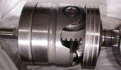
| Cut away view of transmission unit |
Technical Information:
The AP (Automotive Products) Automatic Transmission was first introduced
at the Earl's Court Motor Show in 1965 and debuted in the in the Austin and Morris 1100's beginning in October 1965. It
is the result of a 10 year joint project between the Automotive Products Company Ltd. in Leamington Spa, Warwickshire, England
and the British Motor Corporation Ltd. in Longbridge, Birmingham, England. This unique transmission
has many achievements:
- It is possibly the only automatic in the world to run on engine oil.
- It was far ahead of it's time and won the Queen's Award to Industry at the 1965
motor show.
- It is considered the forerunner of the modern "automatic/manual" transmission.
- It is considered the first automatic fitted to a transverse mounted engine.
- It is considered the first automatic fitted to a mass produced compact car.
- There have been numerous upgraded versions of this transmission and it was still in production
for use in the Mini and the Metro until 2001.
- An internal auxiliary pump allows the vehicle to be tow started.
The version used in the Austin Americas is considered a MK II version. It uses about 9 quarts
of 10w/40 engine oil on initial fill, and about 6 quarts thereafter for oil and filter changes. I strongly recommend
that the oil and filter be changed approximately every 1,000 miles! Only use 10w/40. I also strongly recommend that
the engine/trans not be stored with "old" engine oil inside. The contaminants in dirty engine oil will attack and damage
the nitrile (buna N) O-rings and seals inside the transmission. Change the oil and filter before storing the car.
There is no "Park" feature, but it does have starter lock out switch to keep the engine from
being started in any of the drive gears. Therefore the parking brake must always be used to hold the car from rolling away
when parked. The transmission has an auxilary pump which is driven when the car is rolling and it will start the engine
if the car is towed faster than 20mph if the transmission is placed in any of the forward drive gears.
Due to the design of the transmission, the car can not be towed with the front wheels on the ground.
The owner's manual actually says you can tow at low speeds and for very short distances, but why risk damage?
The transmission can be shifted manually by simply selecting the desired gear with the gear shift
lever. This function overrides the automatic feature and will hold the transmission in that selected gear, no matter
what the engine speed or road speed.
My recommendation is that you leave it in "D" and let the transmission take care of itself.
Rebuild Parts Order:
The only source in the world for AP Automatic Transmission Parts is "JPAT" in England. Visit
their website at: http://www.jpat.co.uk/ Telephone them at: 1954-852772
I highly recommend you phone them directly as they are very nice to deal with, and that will get
you the fastest and most accurate service. A word of advice; many British firms aren't eager to use email, even if they
offer it. They still prefer talking on the phone. So, if you send them an email (and I wouldn't), don't be surprised
if it takes a while to hear back from them. Another bit of advice; be polite and patient. You'll have a much better
experience with anyone from the UK and quite frankly, if you come off as just another rude, demanding American, you probably
won't get any help or parts at all.
To do a complete rebuild, you want:
1) The "Master Rebuild Kit."
2)
All 3 brake bands (and do send yours back because they are becoming scarce!)
3) One extra "friction
disc" and one extra "steel disc" for the forward clutch only if you intend to do the "3 plate modification"
that I outline below.
4) All of the "metal sealing rings" if they are not included in the master
kit
5) All of the "rubber clad oil seals" if they are not included in the master kit
Ask
them not to ship it FedEx. Have them simply send it airmail via their "Parcel Force."
Parcel Force will get it
to your door in about 10 day, via the regular US Mail, with no customs charges.
One warning about customs: Make
sure they put on the invoice that the total parts bill is UNDER $400US. This will ensure there is no customs involvement.
Have them split your oder into 2 packages if they have to, in order to keep things under $400. If you wind up
having customs involved, you'll get screwed beyond belief by the pirates that syphon off fees for paperwork, power of attorney,
and storage while you figure out what to do.
You don't need the frictions for the Top Gear/Reverse Gear pack. They
are bronze clad and don't wear out. In fact, the frictions you'll get for the forward clutch are the better bronze clad
version. The bands are also updated with new Dupont Aramid/Kevlar material.
Don't worry about rebuilding your
torque converter unless you have some symptom indicating it's failed internally.
If your transmission is not working properly, the first test you
must perform is making sure the engine oil (which is shared with the transmission) is at the correct level....at the
MAX line on the dipstick.
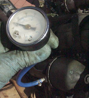
Following this, you need to do a pressure test on the transmission's oil pressure.
The service manuals all show a special dealer tool for doing this. The tool combines a pressure test gauge and a tachometer,
along with enough hose and electrical line to place the unit inside the car and go for a test drive.
For our purposes, we can build a pressure test gauge very easily and inexpensively.
Here's what you'll need:
- A pressure gauge capable of reading 0-160psi
- A foot or two of high pressure hose and 2 hose clamps
- A nylon plastic fitting that is barbed male on one side and 1/8" pipe thread on the other
side.
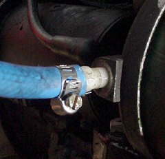
Assemble this pressure test gauge and thread it into the threaded opening on the front edge
of the oil filter stantion. You'll see a bolt in this location. Remove the bolt to gain access to this pressure
test port. The threads are actually 5/16" x 28pitch fine thread. Good luck finding a fitting with those threads.
Hence my choice of the nylon plastic fitting. 1/8" pipe is close enough and the plastic will deform just enough to make
a nice fit without leaking and more importantly, without damaging the test port's threads.
With the pressure gauge installed you should get the following results:
- 95-105psi in Neutral and any forward drive gear.
- 142-158psi in Reverse.
| Pressure gauge attachement to front of oil filter |
|
|
| A barbed nylon 1/8 inch pipe fitting will thread right in nicely |
Diagnosing Faults:
The transmission I'm diagnosing and repairing for this technical section has only 29,000 miles.
It has been in a one owner car that has been in storage since 1976.
Statistically, the Americas with AP Automatics rarely made it through their initial 12 month/12,000
mile factory warranty period without needing a major overhaul of some sort. They generally failed completely at or before
30,000 miles.
This transmission will not engage Drive, or 1st, 2nd, or 3rd gears. However, Reverse works
perfect.
A pressure test showed the operating oil pressure in both the engine and the transmission were well
within tolerance and certainly at the high end of specification. The diagnostic charts in the repair manuals say that
if the pressures are normal, then the fault is likely within the "Forward Clutch Assembly."
Indeed, upon speaking with quite a few people who are knowledgeable about these AP Automatic Transmissions,
I learned that the forward clutch assemblies were the weak link and almost always the cause of failure.
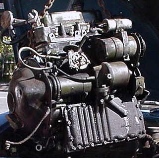
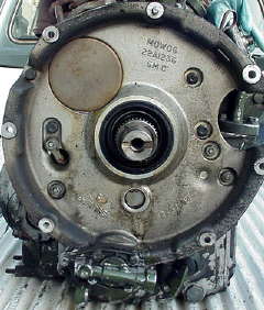
The Forward Clutch is easy to access and repair, but unfortunately, it can only be done with
the engine/transmission removed from the car. So, the next step is removing the 500lb. greasy lump and then steam cleaning
it.
|
|
| The automatic eng/transmission unit |
|
|
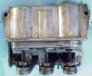
| The Forward Clutch is behind the Govenor Housing cover |
Forward Clutch Repair/Modification:
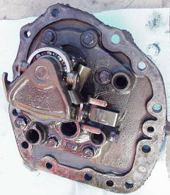
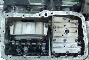
Removing the end cover reveals the auxiliary pump and govenor (left photo) and the forward clutch
assembly (right photo). Not the alignment of the copper oil feed pipes. To remover the Forward Clutch, remove
the lower oil feed pipe by twisting and pulling toward you. Remove the pump screen. Pull the Forward Clutch straight
out, then turn it to your left to get past the upper copper pipe. Remove the circlip on the Forward Clutch and you can
take out all the plates and tiny springs, as well as the big aluminum piston underneath.
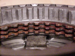
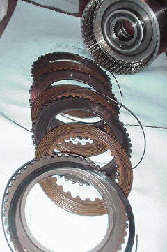
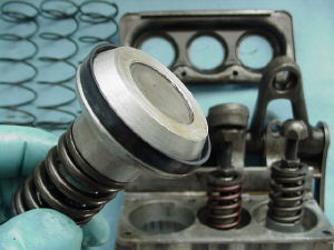
Note how thin the friction material is. New plates are about .102". These were .068".
Note the split in the forward clutch actuating piston seal. From sitting with the same engine oil for 27 years
all the rubber seals and O-rings inside this transmission are hard and brittle like plastic. Most are damaged and not
sealing properly.
| This is sensative to speed and foot position |
|
|
| The Auxilary Pump and Govenor |
| The Forward Clutch |
|
|
| This drives the forward gears |
| Forward Clutch Assembly |
|
|
| 2 friction plates are sandwiched in here |
| Clad with a paper-like material |
|
|
| Forward clutch plates very worn |
| Old dirty oil damaged this seal |
|
|
| This rubber seal is now hard and has split |
Forward Clutch Modification:
Here are two tips that I've been told about.
- Replace the "stock" forward clutch friction plates, which are lined with a paper-like material, with
the plates from the top/reverse gear assembly. The top/reverse gear friction plates are lined with a much more durable
material and will handle the loads in the forward clutch much better. In fact, you can now only buy one style of friction
plate for the transmission. So, this modification is a no-brainer.
- The second tip comes from Rick Lovett, Service Manager at the Monte-Shelton Jaguar Dealership in Portland,
Oregon. Friend and fellow long time America owner John Quilter, told me that Mr. Lovett was very knowledgeable
about the AP Automatics, so I gave him a call. Mr. Lovett was very generous with his time and knowledge.
His trick is to have the metal plates in the forward clutch machined thinner, so that a 3rd friction plate and second metal
plate can be installed. This effectively increases the total friction surface area by 50%. Mr. Lovett's
own Mini Moke is sporting an AP Automatic with this modification and is still going strong...after 25 years!
Modifying the forward clutch:
I took the complete forward clutch assembly and the forward drive gear to the machine shop. My
plan was to have them shave material off the top surface of the bottom metal plate, take material off of both sides of the
2 intermediate plates that go between the friction disks and finally, shave material off the bottom of the top metal plate
just until the .010" clearance spec. was reached.
Using a magnetic base to hold the plates in place, the machine shop surfaced the bottom plate about
.040". Then, they took about .010" off each of the intermediate plates (.005" each side). They then started machining
the top plate and test fitting the entire assembly until they could get a .010" feeler gauge between it and the rest of the
plates as the manual specifies.
In doing the maching this way, my goal was to keep the 3 friction plates centered on the cogs of the
forward drive gear. This is how they are in the stock configuration with just 2 friction plates.
Here's a photo of the finished result:
| Modified Forward Clutch Assembly |
|
|
| Here's how it all comes together after machining |
Drive Train/Planetary Gears:
To get to the big drive train and the planetary gears, you need to remove the torque convertor cover,
the torque convertor (which requires a monster sized puller) and then the low pressure valve comes off. After that you
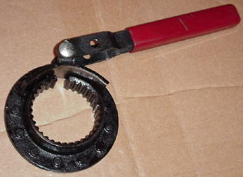
spin off the big input gear nut using a 1/2" drive air gun (or a breaker bar if you've made the tool for holding the primary
gear staionary). Then you can remove the drop gear housing, primary gear, intermediate gear, and input gear with shims.
Do yourself a favor and put the gears in individual zip-lock bags so they stay clean! Put them
in a save place so there's no chance of them falling to the floor.
The gear train can now be removed. Undo the locating bolt that's on the back of the transmission
case near the 9 O'clock position on the side of the gear train. Now the gear train can be jiggled and slide
right out. This takes some finese and some minor shaking of the heavy gear carrier. The brake bands sort of drag
on it makinging it difficult to remove.
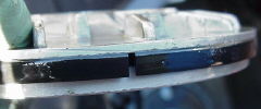
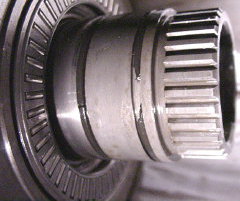
Once it's out, you can pull the top gear assembly off the end. Check the condition of all 3
O-rings. As you see in the photo below showing 2 of them damaged. The third one is visible after you remove that
gear.
Watch out for the location of large thin washers and needle roller bearings, and their orientation.
This is a good time to be reading your manual and taking note of all the parts and seals that make
up this major assembly.
As you can see in these photos, bad O-ring seals was a problem throughout the transmission.
| The other end of the transmission |
|
|
| Torque convertor has been removed already |
| Remove the Low Pressure Valve |
|
|
| Then undo the input gear nut with an air gun |
| Drop gear housing removed |
|
|
| There are 2 seals where the primary gear pokes through |
| Drop gears |
|
|
| Primary gear Intermediate gear and input gear |
| Tool for holding Primary Gear |
|
|
| Manual trans clutch disk hub welded to a handle |
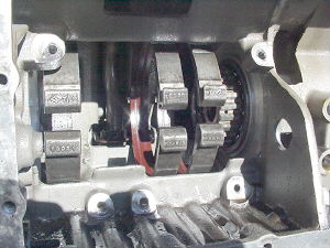
| Planetary gears of the gear train assembly |
|
|
| Top and reverse clutch assembly is removed |
| More seals damaged |
|
|
| These are where it fits into the Top Gear clutch |
|
|
| Top and Reverse Gear Clutch Assembly |
Valve Body & Brake Band Servos:
To access these last two components, simply remove the front access panel on the transmission.
To do this, you'll need to remove the external engine oil pipe along with the pipe fitting that connects
it to the top of the transmission case near the oil filter housing. Once the fitting is out, you'll find a brass feed
pipe. It has sort of a zig-zag shape and can be twisted while pulled up and it will come out of the valve body.
Now you can remove the entire front panel on the transmission, complete with the oil filter housing
assembly.
Now you'll need to take out the shift rod that runs all the way across the transmission.
First push it all the way inward. Then take a 7/16" open end wrench and grab the coupling that you see it going
into, just to the right side of the valve body. Use a flashlight to get a good view. Hold that coupling.
Now use a wrench on the other end of the rod and unscrew it. It will spin free of the coupling that it's threaded
into and then just pull right out.
Undo all the bolts that hold the vavle body and the brake band servo unit in place. Reach
in through the opening where the big gear train was and unclip the brake bands from the fitting on the servos.
You may find it easier to loosen the adjusters on the servos first to give you some slack on the bands.
With the bands unclipped, pull both the servo unit and the valve body out at the same time, as a
unit. Some short oil feed pipes keep them together at the top, and 3 more stubby feed pipes locate the valve
body in the transmission case. Use care in pulling these assemblies loose!
Once you have them out, seperate them, take them apart and replace the seals in the servo pistons
and all the O-rings on the feed pipes....6 pipes and 12 O-rings. Also, there are O-rings where that zig-zag brass pipe
fit in the top of the valve body and where the forward clutch feed pipe went into the side of the valve body. There
are no seals on the actual valves in the valve body.
The brake bands can just be tipped to the side and pulled out the front of the transmission.
| Brake band servo and valve body |
|
|
| These control the transmission shifts |
| The valve body apart |
|
|
| No seals in here just metal pistons |
| Brake Bands |
|
|
| A view from where the gear train sits |
| Servo and valve body removed |
|
|
| Brake bands are ready for removal |
| Brake Band Servo Unit |
|
|
| This is how it looks assembled |
| Replacing brake band servo piston seals |
|
|
| These are important seals |
Final Outcome & Driveability:
This rebuild has turned out very successful. I spent about $500.00 total and $170.00
of that was for the machining of the forward clutch components. The car is litterally as good or better driving than
when it was brand new and shifts on par with any modern car.
If you've not driven an America with an Automatic, you're definately in for a treat!
They are an absolute joy to drive and this one has turned out to be no exception. I'm very pleased with the outcome
and glad I decided to rebuild it.
- The transmission is very quite other than the whir of the torque convertor, which they all do.
You only hear this whir at low speeds.
- The shift points are all perfect and very smooth. Under light acceleration, like just pulling
out of your driveway and driving down your residential street it shifts from 1st to 2nd at about 8mph, 2nd to 3rd at
about 15mph and into 4th at about 20mph. The shifts are so smooth, you can barely feel them. Once in 4th, the
torque of the engine easily pulls the car around town at any speed.
- If you need more power and hence depress the accelerator pedal a bit, the transmission will kick down,
all the way to 2nd if need be.
- As the car slows, the transmission shifts down, and will go all the way to 1st as you come to
a stop.
- Under hard acceleration, as in holding the accelerator to the floor, the shift points are raised significantly
and the their engagement is very noticable with a nice kick that you can feel.
- There is no "3rd to 4th Flare Up" that the service bulletins all speak about as being a problem back
when the cars were new.
- The car easily accelerates to 65mph getting onto the freeway and will comfortable cruise at that speed.
70mph is also quite comfortable and there is plenty of power for passing or climbing hills.
Having now rebuilt one of these automatics, I would do another the same way without any hesitation. Having
now driven one, I wouldn't hesitate for a moment to own one and drive it everywhere. I think the internal components
are extremely large and well built, especially considering the fact that they only have to sustain about 50hp running through
a slipping torque convertor.
I'm confident that with these modifications and regular oil and filter changes at 1,000 mile intervals,
these transmissions can be as dependable and durable as the 4 speed manual transmissions.
I'm looking forward to the first oil change so I can compare the look of the oil and the quantity of
"metalic fuzz" trapped on the magnetic drain plug, with how the oil and drain plug look in my 4 speed manual transmission
cars. I'm guessing there will be almost nothing on the drain plug magnet and that the oil will not be metallic
looking because their just aren't all the gears, shims, syncros, layshaft and other components that wear so heavily in the
manual transmissions. I'll post the results here.
Update:
2 months after the rebuild and I have put a little over 200 miles on the car. Most of
this has been around town running errands and other regular daily type usage. I've done a couple 15 mile out and
back blasts on the freeway. It gets right with the program when accelerating onto the freeway and easily keeps up with
traffic. It has been fantastic and there have been no problems. It is still just as much fun to drive as it was
the very first day it was back on the road.
At this mileage, I changed the oil and filter right before selling the car. The magnetic
drain plug had a "normal" amount of metalic fuzz, but the oil was clean and clear. I was surprized that it took
almost 6 quarts of 10w/40 weight oil to fill it back up. I was thinking that only about 5 quarts would be needed.
I have done one driveability adjustment and it has made a huge difference in acceleration power.
I noted when reading the AP Automatic Factory Service Manual that the shift point specification given for 3rd to 4th
under full throttle was 56mph with a window of 4mph in either direction. So basically, 52mph-60mph at full throttle.
This transmission was actually shifting out of 3rd and into 4th at about 47mph. That early shift was
really keeping the engine from winding up and making some good torque and horsepower, especially when merging onto the
freeway at speed.
The AP book states that the kick down rod, which runs from the carburetor linkage down to the bell-crank
on the back of the transmission, can adjusted "shorter" (in other words, screwing it into the plastic heim joint
connector at the bellcrank) to raise the shift point speed. I loosened the little locknut and turned the kick down rod
inward 5 turns and this raised the shift point to about 53 mph. I left it like that and what a
fantastic gain in the power produced under full throttle.
The engine pulls much harder through all the gears because their shift points are also raised.
This effectively keeps the engine up in it's power band and by the time it shifts into 4th, it's really pulling
nicely. An easy and very rewarding little bit of tuning.
I think one of these automatics could produce nearly as good as a well tuned 1275 with manual gear
box. A torquey cam like the Swiftune SW5 or the Kent 256, 1.5 ratio forged rockers, larger diameter exhaust, CN
carb needle, K&N airfilter and modified intake tube would really liven one of these up.
Update June 1, 2004:
I have a couple of Register members who've recently removed the torque convertors in order to replace
their leaking torque convertor seal. Following this, they both had oil leaking from the 6 torque convertor bolts that
are located in the center of the convertor. These bolts actually go through the metal skin of the convertor and thread
into the center hub of the stator inside the convertor.
The service manuals say to NEVER remove all 3 of these bolts at the same time. Only remove
3 of them in order to fit the torque convertor puller. One of these Register members had removed all 6, the other only
removed 3. However, both have the same leaking.
We've been exchanging quite a few emails trying to figure out how the leak is occurring and
come up with a way to cure it. Finally, I think we have a solution. My friend Steve Slivinsky, Register member
No. 6, in Neenah, Wisconsin has been successful in stopping the leak. His instructions are posted below.
Thanks so much Steve!!!!
"I didn't have the heart to tell you yesterday that I fired
up the Austin after sealing everything up with Yamabond - and still had considerable leaking.
Once it started leaking, I shut her down and took out the
small bolts to find oil behind them/on the back of the locking tab. Looks like the locking tab is allowing oil to leak outwards
up past the bolt threads. The Yamabond doesn't work too well on non-machined surfaces.
(Maybe those darn locator pins are leaking??? Little silicone
inside them and on their surface. Let her dry overnight. - Next day, still leaking.)
So, today I went to the hardware store, got slightly longer
ss bolts, grade 8 flat washers, grade 8 lock washers, & gasket paper.
I cut a gasket for behind the plate and punched it 1/4"
dia, so that the bolts would have to be threaded through the new gasket. I applied Aviation Form a Gasket to all surfaces,
including the bolt heads.
Fired her up---better, but still leaking.
Hey, maybe the bolts are just a tad too long.
(What I thought was a large amount of oil leaking was actually
some oil + gasket sealer.)
Replaced the bolts with the original ones.
Fired her up--better, but still leaking!!!DAMN!
Wait a minute--How well do you think a lock washer seals?????
NOT
Took out the lock washers, left on the flat washers, not
locking tab, gasket and Form a Gasket on the threads----No leaking
Yippee.
I always keep a good supply of Q-tips in my toolbox for
locating oil leaks and cleaning up internal threads--they really helped me find the leaks.
I don't think that I have to worry about the bolts loosening
up--at least not this millenium.
Problem solved - I hope."
Update June 4, 2004:
I have several pieces of information that I'd like to share in this latest update:
First, I've been told by some very knowledgeable sources that the oil filters for the AP Automatics
used in the Austin America (which are larger than those used in the Mini) are no longer being made and are becoming extremely
difficult to find. I believe I've found a viable solution, however, I've not personally tested
it yet. However, a Register member has, and it has worked.
I've found that the Triumph TR-6 oil filter is nearly identical. The rubber o-ring that comes
with it is the exact same size as the one used in the automatic filter, but the Triumph filter is about 1/8" smaller in diameter
and 3/8" shorter in height. The Triumph filter does have the same inside opening where the stepped washer and large
securing bolt go through. The spring inside the filter assembly that keeps the filter pressed inot position, may need
to be stretched just a bit to compensate for the 3/8" height difference. See the comparison photos below for a better
idea of how they compare.
| Width comparison |
|
|
| The TR6 filter is the green one |
| Height comparison |
|
|
| 3/8 inch difference in height |
| Opening comparison |
|
|
| Openings are identical |
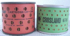
Additional oil filter information provided by MG1100 owner Tom Johnson: The Austin America paper cartridge
filter available at www.7ent.com part number : GFE0122. But they aren't cheap. (30 bucks) Thus
the following possible alternatives: I found this info on the side of an old Jones Filter oil filter box that I had on the shelf.
Cross reference oil filter numbers are: AC 79, Crosland 632, Fram CH2844, Purolator MF 586A; Uniparts GFE 122; GUD
Jones filtration G.752; On a unipart GFE 122 filter box I also had on the shelf I
found I had hand written WIX 51184; Beck Arney 0418913 for cross reference
Second, is the continued durability of the transmission that
I rebuilt for this tech section. In May the new owners of the car participated in the 488 mile, 2 day, Alpine 500 road
rally. This fantastic yearly event takes entrants on a road course from downtown Sacramento, California up
to Lake Tahoe and back in 2 days. Normally, this would be about an 80 mile drive, one way. Not on the Alpine
500!
The new owners pushed the car to it's limits, even loosing the brakes at one point on Day
1. But, they had no problems with the transmission. In fact, on day 2, they were following me on a section
of freeway at about 80mph! The Alpine 500 (www.alpine500.com) is a very hilly course, winding it's way through the mountains at elevations of over 7,000'. Most of the
course is twisty and technical and I know the automatic was working like crazy shifting up and down the entire time.
It was great to see the car perform so well under some very severe driving conditions!
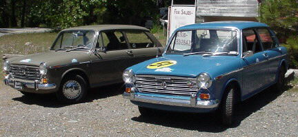
| Day 2 of the Alpine 500 |
|
|
| Our Americas take a much deserved break |
Update December 14, 2006:
I have just received emails from Dick Elg in San Diego, CA. Dick was involved with BMC/BLMC
and Austin Americas from the very beginning and is credited with selling the very first Austin America in the United States!
!n 1968, Dick was working for "College Motors Sports Car Center" in San Diego, CA and he later became
the Service Manager at "Conway British Imports" also in San Diego. It was here that he met Garth Howell, the West Coast
Service Representative for BLMC.
Garth came up with an "unauthorized" solution that solved the oil leak from the torque convertor.
The original seal was just the micro-machined finish between the tapered crankshaft end and the inside of the torque
convertor (TC). When the TC was removed, there would sometimes be a transfering of material between the two surfaces.
When this ocurred, the result was a leak (as you've read above).
Some dealers when so far as to have a groove machined in the crank so that an o-ring could be fitted.
This did not cure the problem and ultimately BLMC recommended replacing both the crankshaft and the TC. (And we wonder
why the Americas vanished from the face of the earth so fast!)
Garth came up with a viable solution that worked. He would coat the tapered crankshaft end
with shelac, then wrap with 2-3 turns of toilet paper, and then put on one more coat of shelac. With
the shelac still wet, the TC was installed. Problem solved!
Many thanks to Dick Elg for providing this information!
|