|
Engine/Transmission/Clutch:
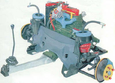
| The 1275cc A-series engine & transmission |
|
|
| The heart of these great cars! |
Although these components are dealt with seperately
in the manuals, I'm going to group them all together since they are all part of the same assembly.
Since everyone
has their own ideas about how to build and work on engines, I'm simply going to share my methods and discuss some of the "drive-ability"
issues that I've resolved. Hopefully, some of my experiences in owning, driving and working on the car since 1983 will help
you with a problem you're having now, or may come across in the future.
Converting an Automatic Block to Manual Transmission
Block:
This tech tip offered by posters on the Mini Mania/Mini Spares Message
Board:
An hour on a milling machine table will make that block indistinguishable
from a manual block. Here's what needs to be done:
- Drill out the 7/16" dipstick hole.
- Remove the Oil Pressure Relief Valve Seat. The seat (which
sort of looks like a metal spool) is cross drilled so you either need to braze or weld up the cross drilled openings,
or simply replace the seat with a new "manual transmission block" one. Leave the seat now because the main oil feed
hole from the seat area down through the block and into the oil pump area can only be drilled (at a slight angle in order
to miss the #4 Cylinder wall) with the valve removed..
- Mill a flat bottom hole, 3/8" dia., 1/4" deep for the oil pump's outlet
port.
- Drill the 5/16" dia. hole from the pressure relief valve to the 3/8"
dia. hole you just drilled for the oil pump outlet port.
- Drill the 5/16" dia. hole from the filter head pressure feed outlet
to intersect the horizontal 5/16" passage from the pressure relief valve.
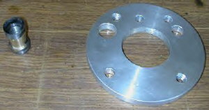
- Make and then install a 1/4" thick spacer between the oil pump
and the block because the Automatic block's oil pump recess is bored deeper than the manual block's.
A Couple of Notes:
- Be aware that the oil pump spacer must be fitted before the main
5/16" oil feed hole is drilled! (You have been warned!) This is because the newly drilled
hole often intersects the spacer. It is most important to seal this area on final assembly, to prevent oil leakage.
- Don't forget the relief valve seat is different on an auto,
it is cross drilled. As noted above, this needs to be pulled out and the X-hole filled, or a manual seat fitted.
- Some of this machine work is tricky, particularly around the oil pump.
Problem
is, the back of auto block is bored deeper than stock for the BIG auto pump. Auto blocks don't have the main oil pump drilling
as they use an external pipe from the pump to the auto valve block.
On all 1275 blocks, the pump oilway alignment
is closer to the rear block surface than on small bore blocks to clear the bigger bores. Note:
By "rear block surface" we're talking about the surface of the block that faces the clutch) This means that
this oilway, when drilled thru to the pump mount for this conversion, usually cuts thru the intersection of the spacer and
the pump mounting face. It's best to set up and drill this hole on a milling machine to ensure it doesn't
wander during drilling.
The way to seal this intersection is ensure the pump spacer is a real neat fit in the block,
and use Loctite 515 Master Gasket when fitting it.
My thanks to my friend Kevin Green in Australia (long time Mini enthusiast and a stellar
mechanic) for providing this information.
| Relief Valve & Adaptor Plate |
|
|
| Braze or weld up the holes in the valve |
| Drilling out the oil galley |
|
|
| Flat bottomed hole 3/8" dia. 1/4" deep |
| The adaptor plate |
|
|
| A couple of threaded holes for ease of removal later |
| Adaptor plate installed |
|
|
| Use Loctite 515 for final assembly |
Many thanks again to Kevin Green for the detailed
instructions above, and these 4 great photos of his recent conversion.
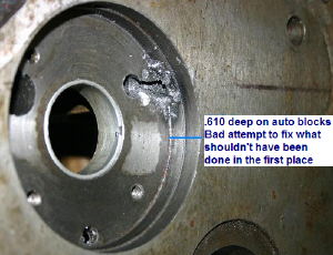
| Drilling oil passage to oil pump |
|
|
| Watch your drill anlge This is what not to do |
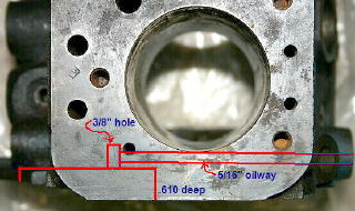
| Top view of the 2 oil gallies |
|
|
| This is what you are drilling out in steps 2 and 3 above |
Thanks to Paul Menges for these great photos of an automatic block.
Gasket Sealers & Glues:
-There are dozens of different products available for use on engine and transmission
gaskets. People's opinions on which to use and when vary widely, and some don't believe in using glues or sealers
at all.
I'm a believer in gasket glue or gasket sealer, and I always use some sort of sealer
on everything except headgaskets. For years I used RTV type silicone sealers, but have gradually gotten away from
them. I've found that they invariably allow the gasket or seal to leak. Plus, I don't like how the silicone squishes
out into the engine or transmission.
Engine/Transmission Gaskets:
A few years ago, good friend, talented British car mechanic and owner of "British Sports
Cars", Peter Jurgens, told me about "Permatex Aviation Form-A-Gasket Sealant Liquid." (NAPA
Part No. 765-1211) I tried it and haven't used anything else since. I haven't had an oil leak
from a gasket that I've installed using this product. Even on old gaskets that I've re-used, I haven't had a leak.
On paper, cork or rubber type gaskets, intake gaskets, etc., I highly recommend this stuff.
Exhaust manifold gaskets:
I use a product sold by NAPA, called "NAPA Exhaust System Muffler and Pipe Sealing Compound"
(NAPA Part No. 35959) This product works excellent on exhaust system gaskets as well as on joints where exhaust
pipes slip together.
Valve Cover Gasket installation:
-Because the valve cover gasket is cork and is not held in position by any means, it can easily
slip out of position during installation and then begin to leak. And, what a leak this can be!
I learned this trick from working on aircooled VW engines: Glue the valve cover
gasket to the valve cover first using a contact cement type glue. The two products I like for this are, "Gask-A-Sinch"
or spray upholstry glue. Both allow you to instantly mount the gasket to the valve cover. However, they
don't establish such a bond that the gasket is difficult to remove during replacement. Coat the other side of the cork
with the Aviation From-A-Gasket. You will not have any valve cover leaks using this method and the gasket will
be easily removed and replaced in the future. I highly recommend replacing the rubber grommets that seal the top of
the valve cover against the 2 mounting nuts. Also, con't overtighten the nuts. This just crushes the grommets causing
them to crack and deteriorate faster.
Engine "Flush" treatments:
-This was a recent topic on our 1100 email chat group and I thought it an important
one to save for future reference. It began when one of our members took their all original car to their mechanic
for a "routine" oil change. The car's owner supplied the oil and filter so all the shop had to do was the labor.
Upon removing the drain plug and finding the usual metal shavings on the magnetic end, they told
the owner that the engine really needed a good flushing to clean out all the crud inside. The trusting owner agreed.
The shop left the old filter in and filled the engine crankcase with diesel fuel and some oil.
They ran the engine for a bit, then drained this out. Still leaving the old oil filter in, they refilled the crankcase
with Automatic transmission fluid and some oil. Again, ran the engine for a while and then drained this mixture
out. This time, they replaced the filter and put in the owner's supplied Castrol GTX 20w/50.
The engine now has only about 35psi oil pressure warm going down the road, and about 15psi at idle.....prior
to this it had 25psi at hot idle, and probably 50 or so at speed.
So, a day late and a dollar short for this owner, here is my 3 cents worth on engine (and transmission)
flushes:
-All the engines got the magnetic drain plugs. And, for good reason!
Look at all the stuff they catch!! I wouldn't sweat the metal pieces too much. They all do it to some degree and
it's just another reason to change the oil more often.
Naturally, there is some suspended crud stuck to the walls of any engine. More so in engines that don't receive regular
oil changes, or just get driven around town so the oil never heats up enough to burn off all the impurities. The last
thing I want to do is flush
all this stuck crud, down through the engine. Why? Because where does it go?
First, it gets sucked up and run through the oil pump vanes. Guess what that does to the tight tolerances
in the oil pump as the vanes get scored. Next it goes past the oil pressure relief valve and can score that piston so
it doesn't seat properly. Then at trip through the oil filter where hopefully all of it is caught, and hopefully the
oil filter bypass doesn't open due to all the crud that's moving through. If the bypass opens it dumps all this
crud directly into the crankshaft and camshaft bearings. On top of all that, the crankshaft and transmission gears sling
all this unfiltered crud up onto the piston walls so the pistons now have a chance to drag up and down in it.
Oil pressure is all about tolerances...and keeping them small. Tolerances in the oil pump vanes, tolerances in
the crankshaft and camshaft bearings, etc. Once those tolerances start to get big...indicating wear/damage...the oil
pressure starts to suffer big time. For example, the crankshaft bearings run on a tolerance of .0015"-.003" By
comparison, a sheet of paper is .004" thick. That's why I freak out when I hear about engine flushing. Imagine the diameter
of the crud particles (mostly chunks of carbon, which is quite hard) that are being flushed around and they go through
the oil pump completely unfiltered. And, if that's not bad enough, oil filters have a bypass function so that they won't
clog up and stop oil flow. So, potentially if an oil filter got hit by a boat load of crud, the bypass could open up
and allow everything to bypass the filter.......next stop, .0015" clearance at the crankshaft. Ouch!
So, in my opinion,
whom ever invented engine flushing (and likewise automatic transmission flushing) is the same guy who wants to sell you a
$4,000 engine rebuilt about 6 months from now. And, that's probably the same guy who will say, "Well, that engine's
30 years old, it's probably all wore out inside," when you come back 4 months later asking why it's knocking and has low oil
pressure at idle.
But hey, call me paranoid. I say leave sleeping dogs lie.
On the flip side, if oil
is getting black before the usual 1,500-3,000 mile oil change interval, then consider changing it more often, do less low
speed/short trip driving, and have the carb mixture checked to make sure it's not too rich.
Engine & Transmission Rebuild Parts List:
The list below is not meant to be the last word, nor the all inclusive parts list. From new
belts and hoses to gasket sets, there are a ton of new parts to order when rebuilding the engine and transmission.
This list is just the "specialty" items that I install and I can highly recommend them all.
I build for low-end torque, high speed freeway (80mph sustained) and low compression so it won't
blow the headgasket, overheat, or ping under full throttle. The list below along with some moderate head and manifold
work with your die-grinder will get you there.
Engine:
Cylinder head:
-Stellite exhaust valves
-Hardened exhaust seats
-Cast iron valve guides
-Stock single valve springs
-Viton Valve Stem seals on all 8 (you can purchase these from me. Email me for more info
at: austinado16 at cs dot com)
-"Mr. Gasket"
brand Heavy Duty 180degree high flow thermostat (from someone who sells american car stuff, like NAPA, Car Quest, etc. Get
the one for the Chevy 350v8
Block:
-Mini Spares
High Flow water pump
-AE slipper skirt pistons, dished alittle, about 9.4:1 compression. There
is also an 8.8:1 set available, which is the stock compression ratio.
-Kent 256 cam with lightened lifters
-Alternatively,
the Swift tune SW5 cam is supposed to be an even better lowend torque, around town, smooth idle and fast road/freeway cam.
-Duplex timing gears and chain (no need to get the lightened versions)
-Mini Spares High Flow oil pump with drive
to match the drive in the cam you use
Transmission:
-Centered oil pickup tube
-Long reach magnetic drain plug
-3.1 final
drive gear set
-Rebuild the whole differential since you'll have it apart:
- New fiber washers a must.
- New bronze washers...the later "A+" ones have a tab that keeps them from spinning.
- New bushings for the output flange covers in the transmission and have them machined
so the output flanges are a snug push fit by hand, they'll loosen right up.
- New hardened layshaft and needle bearings for the lay gear in the trans.
- New 3rd motion shaft bearing.....a must!
-New Rover syncros in the trans!! Do all 4 and it will shift like a dream.
-New clutch disc and pressure plate and throwout bearing and throwout plunger and clutch arm and clutch slave and
slave flex hose
-Measure all the shimmed tolerances in the for
the laygear, primary gear, and intermediate gear and build to the tightest tolerance!
Don't lighten any thing.
Spinning heavy parts will make great torque, torque means power. Do balance the conrod/piston assembies....at least
on a beam type scale.
Convert to spin on oil filter from MG Midget.
Consider ARP head studs, nuts and
washers
Payen/Rover head gasket (will come in the Payen gasket set)
That's the short list. Add a set
of Keith Dodds forged 1.5 ratio rockers to really enjoy the cam, without affecting the smooth idle at all and be sure to add
.003" gap to the valve clearance spec'd by the cam's manufacturer.
You'll need a BQ needle to get you started, (if
you have a fixed needle carb) and you may want to step up to the CN needle that I run once you get some miles on it. ATF
in the carb dashpot.
Removing the Engine & Transmission:
Here's the method I use to remove the engine and transmission,
as a unit and out the top of the car. I try to work in a circular motion around the engine bay, starting
at the top and working toward the bottom, then I go underneath:
- Remove battery and tray (tray bolts are inside
inner fender).
- Remove ground strap from clutch housing to inner
fender.
- Remove clutch slave cylinder from top of housing
(2 bolts).
- Remove starter.
- Remove generator, coil is usually mounted here
too.
- Remove distributor cap and wires.
- Remove 3 bolts & nuts that hold the front engine
mount to subframe.
- Remove the single nut on the back of the front
motor mount.
- Label and disconnect the engine's wiring harness.
- Disconnect heater hoses.
- Disconnect heater cable.
- Remove air filter housing.
- Remove carburetor.
- Remove radiator, hoses and fan.
- Disconnect exhaust manifold or header from the
exhaust system and remove it.
- Disconnect and remove inner U-joints.
- Remove bolts & nuts for clutch housing mount
to subrame.
- Remove 1 nut on back of rear engine mount where
it goes through the subframe.
- Remove the 4 top bolts at the Remote shifter/sandwich
mount.
Thread a bolt into the side of the block just below the heater tap (you
engine hoist chain will go here. Use the rear bolt hole, not the front one that you currently have an engine steady bar bolted
to. Put the other end of the chain over the Generator's lower adjustment pivot bolt. This should balance the engine
nicely for removal.
I don't take the hood off, just put your hoist down close to the engine and as it rises, push the
hood up on the slack in the hood prop.
Some people like to leave the radiators on. I remove them because I don't
want to risk damaging them.
Starting & Breaking In A Rebuilt Engine:
Here's what I was taught by some excellent engine builders and mechanics, and
what I have always done:
If you've installed a new camshaft, and new lifters, then you need to "break in the cam."
The big issue here, is that if you let a fresh cam sit and idle, it's turning so slow that it will grind of it's
lobes in a matter of minutes and be ruined. So, you must "spin it" fast in order to make the lifters spin on the lobes
and wear in the way they should. The other import factor is that you should have assembled the cam and lifters
with "cam lube" to help protect during this initial break in. "Crane Cam Lube" is an excellent product for this.
The
rule is: 2,000rpm for 20 minutes, and absolutely NO IDLE time.
That means get the timing fairly close, get your hearing protection on, a pair
of gloves, and some eye protection too. Fire it up and immediately bring it up to 2,000rpm......look at your watch.....and
hold the engine at that speed for 20 minutes. If you have any sort of "situation" where you need to shut it down, you
shut it down immediately and stop the clock. Once you take care of whatever the problem was, start the clock on the break
in where you left off. You don't start the clock all over again. Remember, it's 2,000rpm for 20 minutes.
Not 2,000rpm for a continuous 20 minutes.
What I like do during the 20 minute run, is to adjust the idle screw,
or put a piece of fuel hose, etc. in the throttle linkage so the engine is held at speed. That frees me up to monitor
the coolant level with the radiator cap off and top up as needed until all the air is purged (remember to open the heater
valve fully during this time so coolant can circulate through the car's entire system!), and I can look all around the engine
to check for leaks or other problems (glowing exhaust from timing that's too retarded), monitor the coolant and oil gauges,
etc. It's nice to be able to stand back and watch it run and not be sitting behind the wheel wondering what's happening
out front.
Following the 20 minute cam break in, immediately dump the engine oil and change the filter. Fill
the filter up with oil before installing so the engine doesn't have to go without oil for any longer than needed during the
next start up. Before starting it again, retorque the head bolts and check/adjust the ignition timing. You
can go drive it a bit, but I'd recommend adjusting the valves, before doing any serious driving. This means letting
the engine set for several hours for it to be cold enough to get an accurate valve adjustment.
After that, use the
"drive it at varying speeds and loads, no full throttle, no high revs, nothing over 55mph" routine for 500 miles.
At which point you dump the oil and filter, adjust the valves, check everything else, and then you can drive it normally
from then on.
Starting An Engine That's Been Sitting For Years:
Here's my method for starting an engine
that's been sitting for any amount of time. Remember the key thing to think about is how do you get lubrication to the
engine's bearings and piston skirts the fastest and with as little harm as possible. The key is to take the load off
the engine by removing the spark plugs. Don't even do a compression test until you've first achieved oil pressure!
- Remove the spark plugs
- Squirt some oil in the bores. Actually I prefer ATF (automatic transmission
fluid) because it's thin so it gets down into the rings easily and it's high detergent so it can help unstick the rings
if they're jammed in place by carbon, old oil or rust.
- Remove the banjo bolt on the external oil feed pipe
- Squirt that galley in the block full of oil
- Rotate the engine over by hand a few times
- Put the banjo bolt back in, but leave it loose so oil can leak out around
it
- Crank the engine's starter and let the engine crank until oil starts
to pump out of the loose banjo bolt
- Tighten up the banjo bolt and continue cranking in 15sec bursts until oil
pressure shows on a home built mechanical oil pressure gauge. You can make a really nice gauge using
a 24" grease gun whip hose, an 1/8th x 1/8th pipe thread female coupler and an inexpensive 0-200psi gauge. Or,
if you have a working oil pressure light, wait 'til that turns off.
- Once there's oil pressure, let it spin on the starter for about 30
seconds and watch what the oil pressure does
- If that all looks good, put the plugs back in
- If it's an engine that's been sitting, I prefer to get oil pressure first
before changing the oil. That's because I don't want the engine spinning any longer than necessary without oil pressure.
If I change the oil, then I have to wait for the filter to fill (even if I fill it) and begin flowing.
- Once I get oil pressure, then I change the oil
Regarding sticking valves, you should be fine with the valve train being okay.
If you had a sticking valve, you'll have one hole not pumping any air. That would be pretty noticeable during all the
cranking to get oil pressure.
Once I have oil pressure and have changed the oil, then I pursue starting the engine.
Breaking loose a seized engine that's
Been Sitting For Years:
Many times these engines will be locked up solid from sitting
for years. Typically, this is caused by rust forming in a cylinder or cylinders because the engine wasn't stored properly.
For example: The engine is in the car, but the carb or carb and intake/exhaust manifold have been removed. This
allows moisture into the cylinders with valves that are sitting open. The moisture eventually rusts the cylinder and
the piston is frozen in place. In this situation, a little patience can really
pay off.
I've often take engines that were considered junk and "locked up solid" and broken
them loose. Not only did I get them loose, but I discovered they had no piston, piston ring, or cylinder damage
and they actually started and ran fine!
Here's what works well for me:
My favorite penetrating oils are:
Kroil
PB Blaster
Mouse
Milk (www.mousemilk.com)
Liquid Wrench
Another good penetrant (but I haven't used it yet) is to mix
AFT (automatic transmission fluid) with gasoline. The gasoline is thin enough to really allow the ATF to get down in....then
the gas evaporates.
To break away locked up pistons, find the piston(s) that are
closest to the top of the cylinder. Leave the head on! Fill all of the cylinders with your favorite penetrant.....or
at least put in enough to not just be sitting in the piston dishes. Then fill the cylinders with the pistons at the
top, with ATF (Marvel Mystery Oil is good too).
Next, take off the rocker gear, or relax the valve adjustment
so that the valves are both closed in the cylinders with the highest pistons.
Now gut a spark plug and braze a fitting to the spark plug
base that will accept a zerk fitting. Thread this tool into one of the holes you've just filled, hook up a grease gun
and pressurize the cylinder with grease. The piston will move down......trust me.
Method for engines that already have the cylinder head removed:
This becomes more of a challenge and again, some patience can really pay off.
Pour/spray in enough penetrant so it's over the tops of the pistons and can get down into
the rings. Typically in this "head off" scenario, you'll have cylinder walls that are rusty. The good news is
that they probably won't be rusty down past the top piston ring. The other good news is that you'll 2 pistons up, so
there were be less rust in those cylinders.
Step one: Hone the cylinders just enough to remove the rust
and get to shiny cylinder wall material. This is important because once you get the pistons moving, you DO NOT want
to force the pistons and most importantly the piston rings upward through rusty cylinder wall surfaces. This will break
the rings and probably score the piston skirts. Use your penetrant as cutting oil and hone the cylinders until clean.
Step two: Clean out the mess you made honing. Get
the cylinders nice and clean, as if you were rebuilding it. Then pour in more penetrant. You're now ready to break
the engine loose!
Step three: Put the transmission in 2nd or 3rd gear, release
the parking brake and start rocking the car back and forth against the transmission. Push harder and harder and you
may get the engine to move. If you do, apply more penetrant, clean any rust you expose as you did in step one, and then
get it to turn completely over. Once you get it to turn over, follow the steps above for getting oil pressure, and get
oil pressure with the head still removed!
Step four: If you didn't get it to break loose with step
three, you have 2 more options. Option 1 is to put the cylinder head back on temporarily and use the grease gun pressurization
trick. If that's not an option, there is one final method. The measured use of a BIG HAMMER!
Step five: Split a 2x4 piece of wood down the middle so
it will barely fit into the cylinder. You want it sized to fit on the outer edges of the piston. Place it down
into the cylinder and get a very big hammer (I use a 32oz Ball Peen). Make sure the transmission is in neutral!
Now hold onto the 2x4 and give it a good hard hit. Do this in each cylinder if they are all rusty. If only one
cylinder is rusty, then this is the cylinder to focus all of your attention on, because it's the one that's locked up.
Continue hitting the piston until you see it move. If you don't seen any results after maybe 10 good hits, you can bet
it's not going to break free. You can choose to put the cylinder head on, or you can choose to apply more penetrant
and let it sit for a few hours or a few days.
Removing Air Pump & Related Items:
Removing the Air Pump, or Smog Pump as they are sometimes called, along with all the related pollution
control components is something to consider if you're going to make your car as dependable as possible.
The engine will run much better, have more power, and stop backfiring when you let off the gas.
Another benefit is in how much easier it will be to work on the engine.
A word of caution: Removing pollution control devices may be illegal where you live.
If you elect to remove them, save them in sealed containers so they will work if needed again.
The Air Pump, air rail, and gulp valve are easily removed in about 15 minutes time. Once removed
you will need to plug the openings left behind.
- Plug the 4 ports in the front of the cylinder head using 7/16" X 20 pitch X 1/2" long allen head screws
- Unscrew the vacuum nipple fitting from the intake manifold and replace it with a 5/16" fine thread
bolt and flat washer. (use the washer that was on the fitting)
- Plug the large diameter nipple sticking out from the fitting that rises up from the center of
the intake manifold. This can be a bit tricky because it's such a large diameter. I've found the large rubber
corks sold in hardware stores work well. This fitting is just press fit into the manifold. You can remove it by
grabbing with a pair of pliars and twisting slowly back and forth while pulling up on it. Once off, you could cut the
unneeded nipple off and weld up the opening.....or come up with another creative way to resolve it.
I recommend leaving the crankcase breather system alone, no matter what year car you have. It's
an important and functional item. See the detailed section on this page for specifics of the two systems used.
Crankcase Ventilation:
During combustion, an engine creates fumes and
pressure within the crankcase. The pressure and oil/fuel contaminated fumes have to be vented out of the crankcase or it will
increase to the point that the engine seals are blown and oil leaks occur. These fumes used to be vented to the outside, passively,
by a pipe or hose that was open to the atmosphere. However, to contol emissions, begining in the late 1960's, auto manufacturers
were required to install systems that actively recycled these fumes back into the engine so they could be partially burned
up in the combustion process.
The Americas used two systems of crankcase ventillation and these varied depending
on where the car was sold in the U.S.A. and what year it was sold. The early system only re-burns the vapors, the later
system is able to both store and re-burn the vapors.
Neither of these systems ever had a connection between the valve cover
and the fitting on the air cleaner housing. This air filter housing fitting was left open on the America.
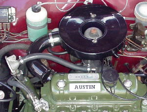
Early Cars:
| California and 49 state cars |
|
|
| 1968/69 Crankcase breather connection |
-The early system used on the 1968, 1969, and early 1970 cars, takes fresh air into the engine
via a vented oil filler cap in the valve cover. The amount of air entering the engine is controlled by a 9/64" oriface
on the inside of the cap. Fumes are sucked out of the engine via a hose connected to the oil seperator, mounted on the flywheel/drop
gear housing. A short 1/2" diameter hose connects the oil seperator to a traditional "Smith's PCV Valve" which is then
connected to the intake manifold. Suction from the manifold draws the crankcase fumes into the engine to be burned.
This system basically creates a controlled vacuum leak into the engine, so if the "Smith's Valve" fails, the engine
won't idle or will idle really rough, or fast. This system was also originally used with an air pump or smog
pump type emissions control system, which is not shown in this photo as it has been removed from the car.
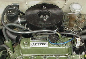
Late Cars:
| California emissions car |
|
|
| 1970/71 Crankcase breather connections |
-The later system, used on 1970 and 1971 California cars, works similarly, but also employs
a vapor storage and recovery system. This additional feature was designed to trap and store vapors from the fuel tank
and engine crankcase when the car was parked. Those stored fumes were later sucked into the intake and burned.
With
this system, a large plastic canister containing charcoal granuals is used as the vapor storage medium. The fuel tank vent
line and a hose from the top of the valve cover connect to the canister, which is mounted on the right side of the firewall.
Fresh air enters the engine via a hose at the bottom of the charcoal canister. This fresh air is drawn up through
the canister, hence removing much of the stored vapors from the charcoal granuals. This incoming air enters the engine through
a hose that goes from canister to the valve cover. A 1/16" oriface in the end of the valve cover breather pipe controls the
amount of air entering the engine. Basically, a controlled vacuum leak.
The oil filler cap used with this system is
a non-vented cap. (Use of a vented cap will cause a huge vacuum leak and very poor idle characteristics.) The engine is basically
a sealed unit with this system. Even the seal at the oil dip stick must be good, or a vacuum leak and poor idle will result.
Crankcase vapors are drawn out of the engine through the oil seperator on the flywheel/drop gear housing and
a second seperator located on the timing chain cover. The seperators were connected to a port on the side of the carburetor
between the carburetor piston and the throttle plate. With this system the crankcase fumes are drawn into the
carburetor rather than into the intake manifold as in the early system.
Oil & Filters:
| Spin-on Oil Filter |
|
|
| Bosch 72150 or similar fits perfect. |
I don't think anything is more important to an engine or transmission
than clean high quality oil. Because these cars use the same oil in the engine and transmission, the condition of the oil
is even more critical. Here are some of my recommendations:
-Use a high quality multi-weight oil that is suitable
for the climate you are driving in. I use Valvoline Racing 20w/50 year round because I live in a very temperate climate.
A lot of Mini owners use synthetic oils in their engines and are pleased with the results too. I'm not sure there is
a pay-off for the added expense of synthetics, because of the frequent oil changes these engines need.
-Change the
oil and filter often. For the manual transmission car, I'd recommend 1,500 to 2,000 mile change intervals. For the automatic
transmission car, I'd recommend 1,000 to 1,500 mile oil change intervals, because nothing destroys an automatic transmission
like dirty oil and contaminants.
-If you have a late car, or have converted your early car to use a spin-on oil filter,
you have the advantage of being able to use some very high quality modern oil filters. You can also use a larger filter that
not only has more filter surface area, but holds more oil.
-I recommend NOT using Fram oil filters. Their internal
quality is terrible, and I have personally known of 2 that have failed. One destroyed an engine and the other caused
a loss of oil pressure unless the engine was revved up. It is worth noting that Fram did not stand behind their filter when
the engine was destroyed. (I have heard of others making similar statements about problems with their Fram filters.)
Click on the link below for an informal, but enlightening study of oil filter quality.
-Because of my experience with
German cars, I have always used German filters. The filters made by Bosch, Mann and Mahle are of excellent quality. The ones
that I use fit the VW gasoline engined Rabbit/Golf/Jetta/Scirocco/Fox/Quantum/Pickup, etc. from '75 on. The Bosch part
number is 72150. This filter is about twice as long as the stock sized filter and just barely fits due to the location of
the reverse light switch on the manual transmission cars. But, with a little finese it goes right on. When using these larger
filters, remember to check your dipstick after the initial start-up because the filter holds more oil (about 1/2qt.).
-Also, as a way to be kind to the engine bearings, I always
fill my oil filter with fresh engine oil before putting it on the car. Then, during initial start-up, I'll start the
engine, let it run a few seconds and turn it off, start it again, turn it off...until the oil pressure light goes out.
That way, I get oil pressure as soon as possible without letting the engine sit and run for 20-30seconds while it fills the
oil filter and then finally sends oil to the crankshaft and camshaft bearings.
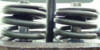
Cylinder Heads & Oil Consumption:
| Compare the 2 seals: Rover on left Viton on right |
|
|
| The viton seal will slide further down the guide |
If you've got an engine, that is using oil,
chances are very good that you have bad valve stem seals. It doesn't matter if the engine was recently
rebuilt. When the OE (original equipment) style Rover valve stem seals fail, the engine will start sucking
oil down the intake guides, burning it while running. Then, after you shut the engine off, hot oil in the cylinder head
will run down both the intake and exhaust valve guides and puddle up on the back of the valve heads. This results in
a big cloud of thick blue smoke when you first start the engine cold. Sound familiar? When the seal wear progresses
far enough, you will also get a big puff of blue smoke under acceleration after sitting at a stop light for a long time.
Or, when decending a long hill with your foot off the gas (creating high vacuum in the intake ports) you will get a big puff
of blue smoke when you first step on the gas at the bottom of the hill.
| Viton Valve Stem Seal Installed |
|
|
| Simply tap into place using a socket |
| Installation comparison |
|
|
| The Viton seal is on the right |
Here's the solution:
Modern valve stem seals made with Viton.
- Viton is designed to be used in caustic and hot
chemicals.
- Viton has a max temp rating of 450*F.
- These seals have the correct dimensions to
fit over A-series engine guides and valve stems, without any modification!
- These seals will fit inside dual valve springs.
- These seals fit either your existing original guides, or
the new guides made of either bronze or steel.
- These are designed to be used on all 8 valve stems.
- These control the oil that gets down the guide, they don't eliminate it.
- These will not cause your exhaust valves to hang up or gall.
If you use them on new guides that have the recessed groove around
the top, then you simply tap them into place using a 12 point socket and 3/8" extension as your installation tool. A
couple moderate taps with a hammer is all it takes to drive them on. They are designed to lock into that groove at the
top of the guide.
If you use them with smooth guides, ie, guides that don't have the
groove, then install them using Loctite Green Sleeve Sealing Compound. Or, simply crimp the base of the seal so it is
oval shape and then tap it into position. The oval shape will make the seal expand back to a round shape and it will
grip the guide perfectly.
ORDER A SET OF VITON VALVE STEM SEALS FROM
ME:
Should you want to order a set, or any quantity,
please send me an email. I've sold thousands in the past 6 years and have not had one complaint. They are
designed to be used with single or dual valve springs. Some of them are even on race engines in Mini's,
and 2 large Mini engine building shops in the UK have been using them.
I can sell you a set of viton valve stem seals for $25.00. That includes shipping in the US.
If you are outside the US, ad a dollar for Canada, or 2 dollars for the rest of the world. If you'd like to make a larger
order, email me and I'll get you a shipping quote.
Installation:
Due to a comedy of errors, I had to remove my cylinder head to install them, but you can install
them with the head still in place:
- Loosen the radiator cap to remove pressure from the cooling system
- Remove the valve cover.
- Remove the spark plugs.
- Rotate the engine so a piston is at Top Dead Center and the valves are both closed.
- Loosen the valve adjustment screws on each rocker and slide the rockers to one side, away from the
top of the valve. You will have to completely remove the #1 and #8 rockers. This is easy as they are only held
on by metal washers and cotter pins.
- Make at tool for holding the valves up in the head or use rope. Stuff the rope into the
cylinder via the spark plug hole, then raise the piston to trap/smash the rope against the valves tightly. Or, use a
hollowed out sparkplug, or a "Leak Down" Tester to put compressed air into the cylinder. Whatever you do, you need to
hold the valves closed, so they don't fall into the cylinder. The rope trick is probably going to be the quickest and
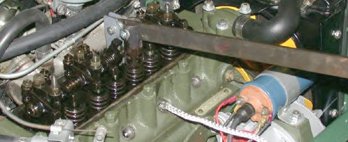
easiest method, as seen in the picture below which was provided by my friend, Mini enthusiast, Doug Lawson.
- Make a tool for pressing the valve springs down. As seen in the picture below, Doug made a very
simple and effective tool. The tool has a hook shaped piece of metal that grabs round the back of the rocker shaft
(that's the silver piece in the photo). Then a piece of aluminum tube with big holes cut in the sides is used to
depress the valve spring and the big holes allow you to get to the valve spring keepers with a magnet. Alternatively,
you can just cut out the front area of the tube and that will still allow you to depress the valve spring and access the keepers
easily. Even a piece of PVC pipe would work here. Either way, use something that your magnet won't stick to.
Thanks for the great tip Doug, and for the excellent picture of your process!
| Easy to make tool |
|
|
| Thanks Doug Lawson! |
Valve Adjustment:
I've recently been asked some questions about adjusting the valves and its been pointed out that
the manual is somewhat unclear on the proceedure, espeically for the novice mechanic or someone who hasn't adjusted valves
before.
Here is the method I use. It varies from the manual's method in that I prefer to do one cylinder
at a time, so that I only have to work on 4 cylinders. The book's method of "The rule of 9" requires you to work on
one valve at a time and therefore you visit each cylinder twice.
A Brief Word About Valve Adjustment Specs.
They should be set to .012" cold and this is the factory spec. Personally, I prefer to set
the exhaust valves at .012" loose, or .013", so that they stay closed longer and have more time resting against the head transfering
their extreme heat.
Happy exhaust valves are loose and cool!!!!! Especially if like me, you like to stand on it
and hold it floored or close too. That pounds the heck out of the exaust valves and seats, so the cooler they
stay, the happier we all are......especially if the head's not been set up for unleaded fuel.
Now, if you have an uprated camshaft, then you must use the cam manufacturer's specifications in order to get full performance/proper
performance out of the cam. For example, my Kent 256 (and the Kent 266) has to be set at .016" cold. Anything
tighter and it will idle very poorly and not make the potential power that it should. It really does make a huge difference......I've
experimented with it! One theory behind this is that "they" want the valves held closed longer to build up a pressure
wave behind the valve. Then, when the valve finally opens there's much more velocity in the air movement, be it intake
or exhaust. More air flow means more power.
Additionally, if you've also changed from the standard stamped steel rockers to the nice forged 1.5 ratio Keith Dodds
rockers, (or spent the big bucks on a set of roller rockers) you need to add an additional .003" to whatever valve adjustment
spec you are using. In my case, I'm setting the valves to .019" cold because I've got the Kent cam and the Keith Dodds
1.5's.
Now onto the adjustment.....
Take the spark plugs out (be
sure to lable the plug wires with a piece of tape or lay them near their respective areas so you get them back on in
the right order). That will make rotating the engine a breeze.
Take the distributor cap off. That
will let you see where the rotor is pointing.....and you want to be able to hold the cap up to the distributor so you can
say to yourself, "Okay, looks like the #1 plug wire lines up with that area on the distributor, so if the rotor is pointing
right there, I know I'm firing #1. You'll be saying the same thing about the other 3 cylinder firing positions.
Make sense?
Now you're ready to adjust the valves......
Put the car in 2nd gear and release the
parking brake. Pull the car forward until the rotor is pointing at #1 plug wire's position. When the
rotor is there, stop. You can now adjust both valves for #1. The outer valve is the exhaust valve so make it just
a smidge loose on the .012" feeler. The inner one is the intake so make it a snug drag on the feeler.
When
you're locking down the adjustment lock nuts, use the largest screwdriver that you have that fits in the adjuster's slot.
Then you have to hold a bit of tension on the adjuster as you tighten the lock nut or the lock nut will drag the adjuster
out of adjustment and it will take forever.
After you've adjusted each of the #1 valves, recheck them! Adjust
again if needed.
Since we know that the firing order is 1-3-4-2, pull the car forward so the rotor is pointing to the
#3 position (about 11 0'clock on the distributor right?). Then adjust #3. Pay close attention to the exhaust valves
for #3 and for #2. These are next to each other in the middle of the head and they share the same port in the head,
as well as in the exhaust manifold. Guess how super heated these and the head gets!!! Here's a good place for a .013"
gap cold. And a good place to make sure that's what you wind up with....so check your work.
Following this, roll
the car forward and check #4. Then roll forward and check #2 and again, be kind to that exhaust valve.
Now......roll
the car forward again, and check your work on all 4. Especially since this is your first time. You want these
right. If they aren't right, they'll be clattering loud, or they'll be so tight that you'll burn an exhaust valve. Additionally,
the car won't run right if they're all jacked up.
The way to have a leak proof valve cover gasket is detailed above.
Follow that method and use Permatex Aviation Form-A-Gasket and you'll have a clean, leak free install. And,
it won't look like a 5 year old was in there with a tube of blue silicone.
Take your time. It will turn out nice the
first time and last you 20,000 miles!
How to tell which valves are which during the adjustment process:
I'll tell you the rule, rather than tell you how they are on your engine, that
way you'll have some better "theory" based automotive skill. Please don't take that as me being up on a pedestal.
It's the "theorey" that will always get you through when you can't remember what some guy told you about your car.
On
all engines, simply look at the manifolds on the head(s). Follow those into the head(s) and they'll point you to "their"
valve.
So face the grill and look at the back of your A-series engine......#1 cylinder is the one over by
the radiator fan.......see where the exhaust manifold mates to the head? It starts at #1 with the exhaust valve
being at the end of the head. Then moving toward the passenger side of the engine you have the intake for #1. Then
look again at both manifolds. What you see is that the intake manifold runner serves 2 cylinders. So you have
an intake valve for #2, then you have the ex.valve for #2, then the exhaust for #3, then the intake for #3, then the intake
for #4 and finally the ex. for #4.
So it's like this as you're facing the engine from in front of the grill...............
EX
IN IN
EX EX
IN IN
EX
#4 #3
#2
#1
Okay,
well, I did show you how it is on your car, but that's okay. You still got the theory.
|