FARM RADIOS
This page takes a while to load, so please be patient.


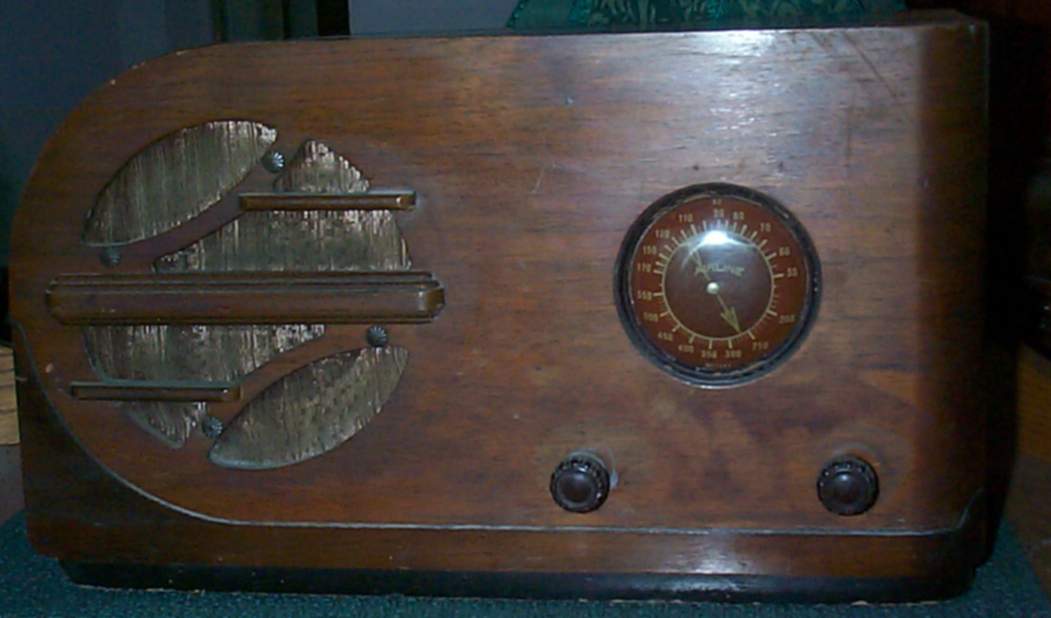
Farm radios are not overlooked in the Art Deco Era,
In fact, some very excellent demonstrations of Art Deco form exist in the catagory of "Farm Radios".
as this Airline 62-324 model shows:
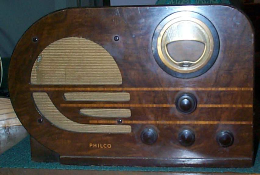
 as well as this Philco 38-38 shows also:
 In fact, some of the "classic" styles, such as "cathederals", "bullets" and "tombstones" had a line powered version, as well as a battery powered farm version.
While performance in their day was a compromise for the sake of extended battery life, the radios often looked better than they sound.
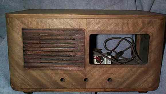
The electro-dynamic speaker
In fact, some of the "classic" styles, such as "cathederals", "bullets" and "tombstones" had a line powered version, as well as a battery powered farm version.
While performance in their day was a compromise for the sake of extended battery life, the radios often looked better than they sound.
The electro-dynamic speaker
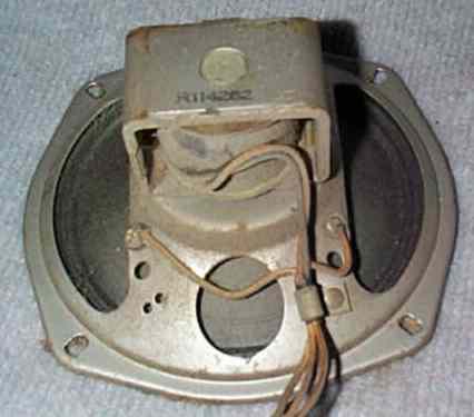 in use on most of the radios where they were able to plug into the earliest power grids- be it in close proximity to milling districts, or well developed cities such as New York required a fair amount of power for operation.
usually the electrodynamic speakers were part of the power supply filtering. The two most comon types of speakers in use on farm radios were the "Permanent magnet" types,
in use on most of the radios where they were able to plug into the earliest power grids- be it in close proximity to milling districts, or well developed cities such as New York required a fair amount of power for operation.
usually the electrodynamic speakers were part of the power supply filtering. The two most comon types of speakers in use on farm radios were the "Permanent magnet" types,
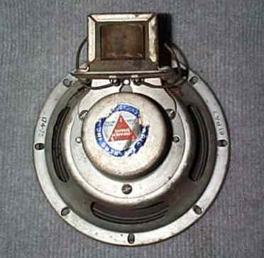 which are the standard speaker design in use today, and the "armature type".
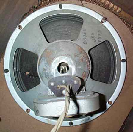 The latter style used a post, called a "pole piece" that is attached to the center of the cone, and had opposing voice coils that were connected into a "push-pull" output amplifier. The term comes from the fact that while one section of the amplifier itself is in a conducting portion of a wave cycle, allowing current to flow through the triode section (or tube)
the coil in the armature that is driven by that half of the amplifier is drawing in the pole piece that is attached to the speaker cone, while the other armature coil is losing it's magnetic field due to the discharging of that coil- which is connected to the other half of the amplifier which is not in the conducting mode at the same point of the wave cycle (as the second triode section [tube] is "shut off").
Both styles are efficient, especially when you consider that your power output was a fraction of one Watt.
As mentioned earlier, design style kept pace with those produced for a wired market, but designs did not stagnate, nor did the selection of frequency ranges.
A "farm radio did NOT mean you were stuck with only "Midwave" reception (today we often refer to it as the AM band.) Philco radios that offered a "Shortwave" band in their "power line operated units, also offered them in their battery powered units too. The same was true across the spectrum of manufacturers. This 1934 Coronado "Tombstone"
The latter style used a post, called a "pole piece" that is attached to the center of the cone, and had opposing voice coils that were connected into a "push-pull" output amplifier. The term comes from the fact that while one section of the amplifier itself is in a conducting portion of a wave cycle, allowing current to flow through the triode section (or tube)
the coil in the armature that is driven by that half of the amplifier is drawing in the pole piece that is attached to the speaker cone, while the other armature coil is losing it's magnetic field due to the discharging of that coil- which is connected to the other half of the amplifier which is not in the conducting mode at the same point of the wave cycle (as the second triode section [tube] is "shut off").
Both styles are efficient, especially when you consider that your power output was a fraction of one Watt.
As mentioned earlier, design style kept pace with those produced for a wired market, but designs did not stagnate, nor did the selection of frequency ranges.
A "farm radio did NOT mean you were stuck with only "Midwave" reception (today we often refer to it as the AM band.) Philco radios that offered a "Shortwave" band in their "power line operated units, also offered them in their battery powered units too. The same was true across the spectrum of manufacturers. This 1934 Coronado "Tombstone"
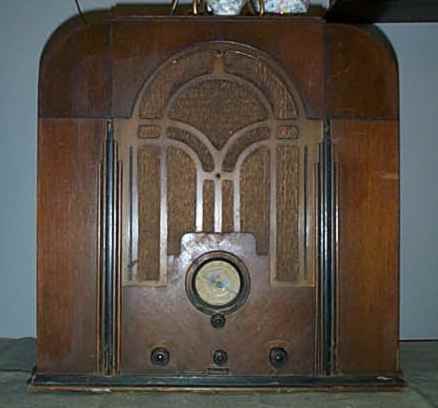 is a prime example of the design lines that were current for the mid-thirties, but the tube complement
utilizes more battery conserving tube types that were always being introduced right along with the other new tubes. In just a few short years, the more common tubes in use will be octal based, (as opposed to the 4 pin triode tubes that had been in use: The 199, 200, 201A, 171A and 112 were the popular types- and for the most part WERE the only types in use until 1926 when the UV224 was introduced by Hazeltine. This Coronado uses 4,5,6 and 7 pin tubes that evolved from those 4 pin tubes.)
is a prime example of the design lines that were current for the mid-thirties, but the tube complement
utilizes more battery conserving tube types that were always being introduced right along with the other new tubes. In just a few short years, the more common tubes in use will be octal based, (as opposed to the 4 pin triode tubes that had been in use: The 199, 200, 201A, 171A and 112 were the popular types- and for the most part WERE the only types in use until 1926 when the UV224 was introduced by Hazeltine. This Coronado uses 4,5,6 and 7 pin tubes that evolved from those 4 pin tubes.)
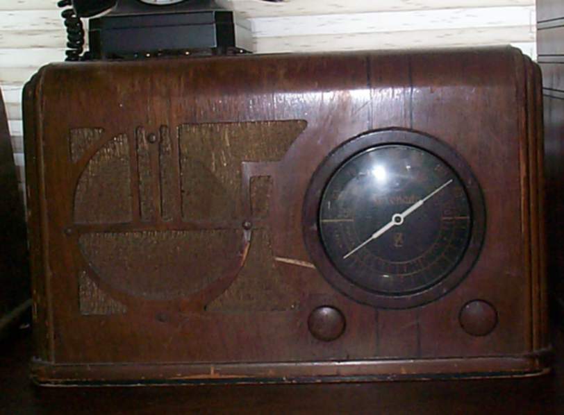 In this 1936 Coronado,
we find the newer energy efficient tubes. In the "Airline Bullet" at top of page, it still has the older tubes, but while it was not the last "new" model to use the old style tubes, it certainly is one of the last.
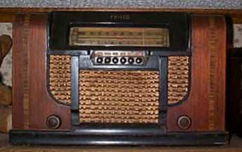
By 1941, this Philco uses the newer energy efficient octal styles, and virtually no one has the older style tubes in prodction radios.
In this 1936 Coronado,
we find the newer energy efficient tubes. In the "Airline Bullet" at top of page, it still has the older tubes, but while it was not the last "new" model to use the old style tubes, it certainly is one of the last.
By 1941, this Philco uses the newer energy efficient octal styles, and virtually no one has the older style tubes in prodction radios.
 After WWII, another shift in even more efficient tube designs were being used. 1A7, 1N5, 1H5, 3Q5, etc, were replaced with tubes such as the 1U5, 1T4, 3Q4, etc. With the exception being in the "car radio adaptations as described below. These miniature 7 pin tubes that were the product of a wartime need for energy efficiency would hold sway until replaced by the transistor.
By the late sixties, almost all farms had been wired into the grid network by the REA, TVA, and other agencies commisioned by the federal government to get the nation wired into an electrical and telephone grid system that we take for granted today, and tubes were gone as a production amplification unit in most household electronics.
Powering these farm radios were often batteries, but there some variations in that some required a "B" battery and a "C" battery in addition to the "A" battery. Others used a device called a "vibrator", which was a circuit interupter that allowed a DC current to become a "pulsed DC current", which would allow for a transformer to increase the voltage potential for the "B" voltage, and the "C" voltage was actually tapped off from the "B" voltage with a voltage divider.
Also fairly common in this era was the "windcharger". Zenith, Montgomery Wards, and Sears made perhaps the vast majority of these, but there were no doubt more than these three, and there were likely many more low production units that would be too numerous to mention.
Consoles were also manufactured, They also afforded a lot of space to place the batteries. Some Philco consoles that were produced in the fities, just prior to the REA's arrival, were actually an automotive Midwave reciever placed in a wood cabinet. I do not have an example show, but of the units I have looked at, they did not look bad compared to their contemporaries, until you turned them around and saw that automotive radio.
I do have a later thirties RCA console, it has needed some extensive cabinet repair, but at this time I am not sure when I may have an image here of it. The style is quite simple, but quite decorative.
When power lines started stretching into the remote farm areas of the Tennessee Valley, The Red River Valley, and other areas that were wired by the REA, those farm radios were not always disposed of, in fact there were many power converters produced even from the earliest days of radio, as this 1925 vintage "B" eliminator attests.
After WWII, another shift in even more efficient tube designs were being used. 1A7, 1N5, 1H5, 3Q5, etc, were replaced with tubes such as the 1U5, 1T4, 3Q4, etc. With the exception being in the "car radio adaptations as described below. These miniature 7 pin tubes that were the product of a wartime need for energy efficiency would hold sway until replaced by the transistor.
By the late sixties, almost all farms had been wired into the grid network by the REA, TVA, and other agencies commisioned by the federal government to get the nation wired into an electrical and telephone grid system that we take for granted today, and tubes were gone as a production amplification unit in most household electronics.
Powering these farm radios were often batteries, but there some variations in that some required a "B" battery and a "C" battery in addition to the "A" battery. Others used a device called a "vibrator", which was a circuit interupter that allowed a DC current to become a "pulsed DC current", which would allow for a transformer to increase the voltage potential for the "B" voltage, and the "C" voltage was actually tapped off from the "B" voltage with a voltage divider.
Also fairly common in this era was the "windcharger". Zenith, Montgomery Wards, and Sears made perhaps the vast majority of these, but there were no doubt more than these three, and there were likely many more low production units that would be too numerous to mention.
Consoles were also manufactured, They also afforded a lot of space to place the batteries. Some Philco consoles that were produced in the fities, just prior to the REA's arrival, were actually an automotive Midwave reciever placed in a wood cabinet. I do not have an example show, but of the units I have looked at, they did not look bad compared to their contemporaries, until you turned them around and saw that automotive radio.
I do have a later thirties RCA console, it has needed some extensive cabinet repair, but at this time I am not sure when I may have an image here of it. The style is quite simple, but quite decorative.
When power lines started stretching into the remote farm areas of the Tennessee Valley, The Red River Valley, and other areas that were wired by the REA, those farm radios were not always disposed of, in fact there were many power converters produced even from the earliest days of radio, as this 1925 vintage "B" eliminator attests.
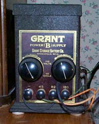 This RCA radio comes with the "optional" power supply.
 For others, there was the "battery eliminator" made by many of the big name manufacturers, and lesser ones too. Below here are a number of circuits that will aid you in powering your own "farm Radio". These power supplies are useful for the really old battery sets of; Freshman, Freed-Eisman, Atwater Kent, Dewald, and many others.
Powering these radios
is often one of the more difficult aspects of owning these types.
Batteries are hard to find, and not cheap,
even if you do make the batteries you need out of 9 volt cells.
< >
The answer is...
the "battery eliminator".
Many were manufactured up into the fifties as the REA (Rural Electrification Agency)
had not wired all of America into the power grid we take for granted today.
The two images here are schematics of mine, one is the schematic for the Grant "B" Eliminator:
For others, there was the "battery eliminator" made by many of the big name manufacturers, and lesser ones too. Below here are a number of circuits that will aid you in powering your own "farm Radio". These power supplies are useful for the really old battery sets of; Freshman, Freed-Eisman, Atwater Kent, Dewald, and many others.
Powering these radios
is often one of the more difficult aspects of owning these types.
Batteries are hard to find, and not cheap,
even if you do make the batteries you need out of 9 volt cells.
< >
The answer is...
the "battery eliminator".
Many were manufactured up into the fifties as the REA (Rural Electrification Agency)
had not wired all of America into the power grid we take for granted today.
The two images here are schematics of mine, one is the schematic for the Grant "B" Eliminator:
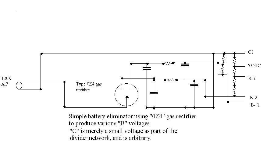
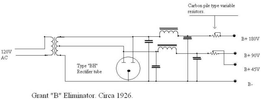 The other is for a generic circuit using a "0Z4", which was common for simplicity. This type used higher value caps, and "RC" networks rather than the "LC" networks of the Grant.
 Values have been omitted for a number of reasons, 1) Simplicity. 2) Liabilities- these are listed for references, and if you attempt to reproduce them, you are doing so at your own risk. (obligatory disclaimer, because you are working with high voltages that can kill you if you do not excercise due cautions.) 3) The values have a wide range of acceptability: Circuits tollerate wide values of resistance and capacitance. For example: The Grant used 2Mfd caps, when I rebuilt it, I used 10Mfd caps.
The RC types (0Z4, and those listed below) use caps that range from 20Mfd to 60Mfd. The "0Z4" unit is just a variation of one of the "B" eliminators below, using a gas rectifier rather than a silicon diode. Be sure to incorporate current limiting resistors into the RC types to protect your equipment from from overloads and fire in the event of a failure of some component in the radio.
< >
Below are some links to battery eliminator construction circuits
I have personally constructed the "B" eliminators, or variations of these circuits with great success.
I will be adding a few of my own in the near future also.
< >
Here are two images of an insert that Raytheon included with a 1926 BH type gas rectifier. top half of insertBottom half of insert.
A reliable and simple "B" voltage eliminator circuit
< >
A hand drawn schematic for an "A" and "B" supply(from above url)
< >
California Radio Historical Society plan for a regulated "A" supply
< >
CRHS "B" supply circuit.
< >
< >
< >
The first link is the one I have made the most variants from,
If you build one that does not quite work right, drop me an e-mail for troubleshooting.
Values have been omitted for a number of reasons, 1) Simplicity. 2) Liabilities- these are listed for references, and if you attempt to reproduce them, you are doing so at your own risk. (obligatory disclaimer, because you are working with high voltages that can kill you if you do not excercise due cautions.) 3) The values have a wide range of acceptability: Circuits tollerate wide values of resistance and capacitance. For example: The Grant used 2Mfd caps, when I rebuilt it, I used 10Mfd caps.
The RC types (0Z4, and those listed below) use caps that range from 20Mfd to 60Mfd. The "0Z4" unit is just a variation of one of the "B" eliminators below, using a gas rectifier rather than a silicon diode. Be sure to incorporate current limiting resistors into the RC types to protect your equipment from from overloads and fire in the event of a failure of some component in the radio.
< >
Below are some links to battery eliminator construction circuits
I have personally constructed the "B" eliminators, or variations of these circuits with great success.
I will be adding a few of my own in the near future also.
< >
Here are two images of an insert that Raytheon included with a 1926 BH type gas rectifier. top half of insertBottom half of insert.
A reliable and simple "B" voltage eliminator circuit
< >
A hand drawn schematic for an "A" and "B" supply(from above url)
< >
California Radio Historical Society plan for a regulated "A" supply
< >
CRHS "B" supply circuit.
< >
< >
< >
The first link is the one I have made the most variants from,
If you build one that does not quite work right, drop me an e-mail for troubleshooting. For powering my Freshman and other radios that use 201a, 301a, etc,
I actually use a 5 volt precision computer power supply. (New tech meets old tech)
For powering my Freshman and other radios that use 201a, 301a, etc,
I actually use a 5 volt precision computer power supply. (New tech meets old tech)
This Antique Radio Webring site owned by
John McPherson.
Random Site [
Previous 5 Sites
|
Previous
|
Next
|
Next 5 Sites
|
Random Site
|
List Sites
]
[
Previous 5 Sites
|
Previous
|
Next
|
Next 5 Sites
|
Random Site
|
List Sites
]
Important
notes:1) Images on this site are copyrighted, and those that I did not create, I have recieved permission for their use.
Any image inquiries can be directed to me via the e-mail buttons.
Thank you.
